Method for realizing reclosing test function of direct-current relay protection tester based on FPGA

A technology of relay protection tester and test function, which is applied in the direction of circuit breaker test, instrument, and electrical measurement. It can solve problems such as reclosing malfunction, electrical equipment hazards in the power system, and wrong action signals issued, so as to solve the problem of reclosing Brake malfunction, simple and clear operation, and the effect of reducing operation steps

Pending Publication Date: 2020-09-22
广州市扬新技术研究有限责任公司
View PDF7 Cites 1 Cited by
  • Summary
  • Abstract
  • Description
  • Claims
  • Application Information

AI Technical Summary

Problems solved by technology

In the prior art, the reclosing device performs the closing or opening action according to the action signal sent by the DC relay protection device (referred to as relay) in the power distribution cabinet. If the DC relay protection device fails in the line, it will send out If a wrong action signal is issued, it will cause incalculable harm to the power system and electrical equipment. Therefore, how to judge the reclosing function of the DC-DC relay protection device connected to the power system is the key to solving the reclosing misoperation problem. , so we propose an FPGA-based method for realizing the reclosing test function of the DC relay tester to solve the above problems

Method used


Image

  • Method for realizing reclosing test function of direct-current relay protection tester based on FPGA
  • Method for realizing reclosing test function of direct-current relay protection tester based on FPGA

Examples


Embodiment example

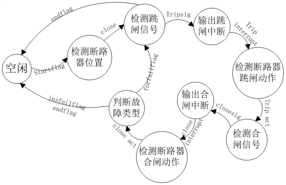
[0036] A preferred implementation example, in step S5, the judgment action for judging the fault type status includes:

[0037] a. If it is an instantaneous current fault (that is, insfailflag=1) or the experimental time limit flag is triggered (endflag=1), the state of the tester jumps to idle and waits for the next start;

[0038] b. If it is a permanent current fault (that is, forfailflag=1), the state of the tester jumps to the detection trip signal and waits for the next operation. If the test time limit flag (endflag) is detected in this state, the state of the tester jumps to idle and waits Next experiment.

[0039]In a preferred implementation case, every time the relay of the tester completes an opening or closing action, the system logic will return an action time to the CPU, and the CPU will upload it to the PC for display, thereby judging the reclosing function characteristics of the DC relay protection device Whether the action time meets the requirements.


PUM


Abstract

The invention discloses a method for realizing a reclosing test function of a direct-current relay protection tester based on an FPGA. The device comprises a tester and a direct-current relay protection device, the tester comprises an analog quantity output port A0, a switching value output port B0 and a three-way switching value acquisition interface BI. The direct-current relay protection devicecomprises an analog quantity acquisition interface AI, a switching value acquisition module BI and two paths of switching value output modules BO, an analog quantity output port A0 of the tester is connected with an analog quantity acquisition interface AI of a direct-current relay protection device (hereinafter referred to as relay protection), a tester switching value output port BO and a switching value acquisition interface BI of the tester switching value output port BO are connected in parallel with the relay protection switching value acquisition module BI, and the other two switchingvalue acquisition interfaces BI are electrically connected with the relay protection two switching value output modules BO respectively. The whole tester device is equivalent to an automatic reclosuredevice on a test site, reclosure function logic is realized by the FPGA by utilizing the parallel processing characteristic of the FPGA, and the tester is utilized to simulate the automatic reclosuredevice, so that the operation steps of the whole test system are reduced.

Description

technical field [0001] The invention relates to the technical field of rail transit power systems, in particular to a method for realizing the reclosing test function of an FPGA-based DC relay tester. Background technique [0002] In rail transit power system, power distribution network is an important part. Due to the wide distribution, complex structure and low insulation level of the distribution network, many defects have been caused in the operation and maintenance, so that the faults on the distribution line occur frequently. The fault types are mainly manifested as transient faults and permanent faults. When the reclosing switch overlaps with permanent faults, the power system will be impacted by short-circuit current again, which is not conducive to the safety and stability of the system. In practice, most faults are Instantaneously, an automatic reclosing device will be installed in the power distribution network in order to reduce the power outage accident caused ...

Claims


Application Information

Patent Timeline
Patent Type & Authority Applications(China)
IPC IPC(8): G01R31/00G01R31/327G05B19/042
CPCG01R31/00G01R31/327G05B19/042
Inventor 王攀常宝波谢悦海张昆周震王晓娜
Owner 广州市扬新技术研究有限责任公司
Why Eureka
Try Eureka