
Drainage tube device

A drainage tube and negative pressure drainage technology, applied in the direction of catheters, suction equipment, hypodermic injection equipment, etc., can solve the problems of inconvenient operation and indwelling, inability to drain drainage for a long time, and materials that are not suitable for long-term indwelling, etc., to achieve guaranteed effect of patency

Pending Publication Date: 2020-09-25
ZHONGSHAN HOSPITAL FUDAN UNIV
View PDF0 Cites 0 Cited by
  • Summary
  • Abstract
  • Description
  • Claims
  • Application Information

AI Technical Summary

Problems solved by technology

[0003] The existing clinical pericardial puncture drainage mainly adopts two devices: one is the central venous catheter drainage, which is thinner and shorter (20cm or 30cm), and the clinical pericardial drainage cannot reach the required drainage site due to its short length, or For hemorrhagic pericardial effusion, the drainage tube is likely to be blocked and cannot be drained for a long time, resulting in poor drainage effect; the other is to use a pigtail catheter for drainage. Although the catheter has a large lumen and should not be blocked, the tube is hard and the patient suffers from pain. It feels heavy, and the length is too long (more than 1.0 meters), which is inconvenient to operate and indwell. In addition, its material is not suitable for long-term indwelling in the body
The above two devices are not specially used for pericardial drainage, and there are defects in clinical use

Method used


Image

  • Drainage tube device
  • Drainage tube device
  • Drainage tube device

Examples


Embodiment Construction

[0025] The present invention will be further described below in conjunction with the accompanying drawings, but not as a limitation of the present invention.

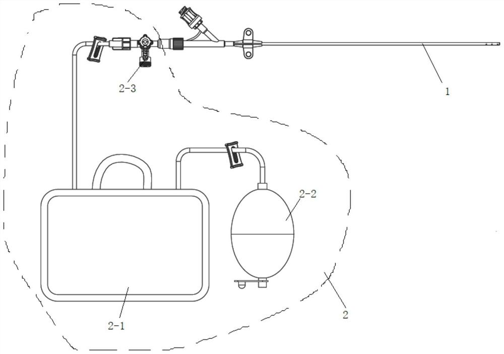
[0026] see figure 1 and figure 2 In a specific embodiment of the present invention, it is designed to include a puncture needle, a guide wire, a syringe, a guide sheath, a dilator, and a drainage tube 1, and also includes: a negative pressure drainage device 2, which is used to suck the liquid flow;

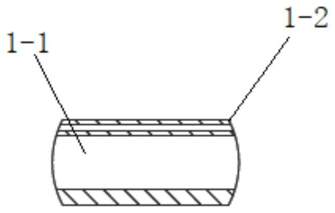
[0027] The drainage tube 1 is a double-layer tube, which is divided into an inner tube 1-1 and an outer tube 1-2, and the inner tube 1-1 is used for hemostasis and flushing of the drainage tube 1 to ensure that the drainage tube 1 is unblocked;

[0028] The outer tube 1-2 is used to penetrate the guide wire for drainage;

[0029] The end of the outer tube 1-2 away from the negative pressure drainage device 2 is provided with an end hole 1-2-1 and several side holes 1-2-2.

[0030] In specific implementation, the drain...


PUM


Abstract

The invention relates to the technical field of medical devices, in particular to a drainage tube device. The drainage tube device comprises a puncture needle, a guide wire, an injector and a drainagetube and also comprises a negative pressure drainage device used for sucking a liquid in the drainage tube to flow, an inner sleeve used for stopping bleeding and washing the drainage tube to guarantee smoothness of the drainage tube as well as an outer sleeve used for allowing the guide wire to penetrate through for drainage, wherein the drainage tube is a double-layer tube and comprises an inner tube and an outer tube. The special pericardial effusion drainage device is designed, the smoothness of the drainage tube can be guaranteed by means of a larger cavity of the drainage tube, and thecircular design of the tail end of the drainage tube can make the drainage tube indwell in a body without stabbing heart tissue; a hydrophilic coating is designed on the outer wall of the tube, so that the drainage tube is more easily sent into a pericardial cavity; and by means of the mated negative pressure drainage device, the outward mobilization dynamic of the drainage tube can be kept, and an effusion can flow outwards continuously.

Description

technical field [0001] The invention relates to the technical field of medical devices, in particular to a drainage tube device. Background technique [0002] Pericardial effusion is the accumulation of fluid in the pericardium and is a common clinical presentation. Clinically, in addition to the manifestations of the primary disease, it is mainly the symptoms of cardiac tamponade caused by a large amount of fluid, mainly manifested as dyspnea, orthopnea, distended jugular veins, and pulsus paradoxus. Acute or massive pericardial effusions can lead to cardiac tamponade, causing acute circulatory collapse, leading to cardiac arrest and death. Pericardial puncture and drainage can alleviate the symptoms of pericardial effusion, and can extract pericardial fluid for analysis to help diagnosis and treatment. It is the main means of clinical treatment of pericardial effusion. [0003] The existing clinical pericardial puncture drainage mainly adopts two devices: one is the cent...

Claims


Application Information

Patent Timeline
IPC IPC(8): A61M1/00A61M25/14
CPCA61M25/0068A61M1/73A61M1/83A61M1/84
Inventor 朱丽潘文志吴轶喆葛均波
Owner ZHONGSHAN HOSPITAL FUDAN UNIV
Learn More