
Posterior cranium distraction and drainage device for neurosurgery department

A technology of neurosurgery and supporting legs, which is applied in the field of medical equipment, can solve the problems of unsafe and convenient use, affect the operation, inconvenient skin and muscles on both sides of the incision, etc., and achieve the effect of easy installation, easy advancement and removal

Inactive Publication Date: 2022-02-01
焦作市第二人民医院
View PDF1 Cites 0 Cited by
  • Summary
  • Abstract
  • Description
  • Claims
  • Application Information

AI Technical Summary

Problems solved by technology

[0003] The purpose of the present invention is to provide a neurosurgery posterior cranial expansion and drainage device to solve the problem that the wall boards in the reference document proposed in the above background technology are arranged on both sides of the posterior skull, but it is inconvenient to expand the incision to both sides. The side skin and muscle and other tissues, and the negative pressure cylinder is located above the affected area, which will limit the operating space for the doctor to perform craniotomy, affect the operation, and it is not safe and convenient to use

Method used


Image

  • Posterior cranium distraction and drainage device for neurosurgery department
  • Posterior cranium distraction and drainage device for neurosurgery department
  • Posterior cranium distraction and drainage device for neurosurgery department

Examples


specific Embodiment approach 1

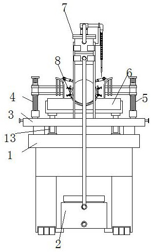
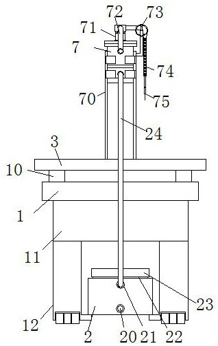
[0034] Specific implementation mode one, refer to Figure 1-9 , the present invention provides a technical solution: a neurosurgery posterior cranial distraction drainage device, comprising a pedestal 1, a liquid storage tank 2, a left posterior cranial distraction mechanism 4, a right posterior cranial distraction mechanism 5, a headrest 6, a drainage Mechanism 7 and head stabilizing mechanism 8, two sets of fixed blocks 10 are arranged on the front and rear ends of the upper end of the pedestal 1, and the upper ends of the fixed blocks 10 are supported on the lower end surface of the operating table 3, and the lower part of the pedestal 1 is provided with a bottom plate 11 , and the left and right sides of the lower end surface of the base plate 11 are provided with two sets of support legs 12, and the liquid storage tank 2 is installed between the two sets of support legs 12 at the front; the upper end front of the operating table 3 is provided with a headrest 6, And betwee...

specific Embodiment approach 2

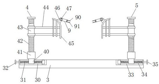
[0036] Embodiment 2. This embodiment is a further limitation of Embodiment 1. In the present invention, the liquid storage tank 2 is used for centralized storage of drainage fluid, and the liquid storage tank 2 is installed on two sets of supports at the lower front of the platform Between the legs 12, it is not only convenient for nearby drainage and storage, but also convenient for pushing and taking out, and is easy to install. At the same time, a tank opening 22 and a twisted cover 23 are arranged on the upper end of the liquid storage tank 2, which is convenient for cleaning and use after opening.

[0037] In this embodiment, a left groove 30 is provided at the left front end of the operating table 3, and a left ball screw 31 is installed in the left groove 30, and the front end of the left ball screw 31 is rotatably connected to the left groove 30. On the inner side wall, and the rear end of the left ball screw 31 is equipped with a left turntable 32, while the front righ...

specific Embodiment approach 3

[0038] Embodiment 3. This embodiment is a further limitation of Embodiment 1. In the present invention, the operating table 3 is an operating table structure attached to the patient's body. Left groove 30 and right groove 33, screw mandrels are all installed in left groove 30 and right groove 33, and the rear end of screw mandrel is all provided with turntable, is convenient to medical staff's manual rotation activity, thereby rotates the inside of it. The screw mandrel is used to drive the movable sleeve on the screw mandrel to move.

[0039] In this embodiment, the left rear cranial expansion mechanism 4 is provided with an upper ball screw 42, and the lower end of the upper ball screw 42 is rotatably connected in the base 41, and the bottom of the base 41 is provided with a first movable sleeve 40. The movable sleeve 40 is movably connected on the left ball screw 31, and the upper ball screw 42 is movably connected with a second movable sleeve 43, the right side of the seco...


PUM


Abstract

The invention discloses a posterior cranium distraction and drainage device for the neurosurgery department, which comprises a pedestal, a liquid storage tank, a left posterior cranium distraction mechanism, a right posterior cranium distraction mechanism, a headrest, a drainage mechanism and a head stabilizing mechanism, wherein the headrest is arranged on the front portion of the upper end face of an operating table, two sets of stroke limiting air cylinders are installed between the pedestal and the headrest, the left posterior cranium distraction mechanism is mounted on the left side of the front part of the upper end surface of the operating table, and a right posterior cranium distraction mechanism is mounted on the right side of the front part of the upper end surface of the operating table; and a concave surface is arranged in the middle of the upper end face of the headrest, the head stabilizing mechanism is installed in the concave surface, a base plate is arranged on the lower portion of the headrest, and the drainage mechanism is installed at the front end of the upper end face of the operating table. The device is reasonable in structural arrangement, tissue such as skin muscles on the two sides of a craniotomy incision of a posterior cranium of a patient can be conveniently distracted to the two sides, the position of the distraction mechanism can be conveniently adjusted, the arrangement of the drainage mechanism does not affect the operation application space, the use and installation are more reliable, and the operation success rate of an operation can be increased.

Description

technical field [0001] The invention relates to the related technical field of medical devices, in particular to a neurosurgery posterior cranial distraction drainage device. Background technique [0002] At present, clinically, after craniocerebral surgery is performed on a patient, the patient's head needs to be avoided as much as possible. Since the intracranial blood vessels are rich and require multi-level separation, there is a lot of bleeding, and drainage after the operation is required. In the reference document "CN201711097116.1 A Neurosurgery Posterior Cranial Distraction and Drainage Device", it is mentioned in the specification that "the base is a "Zhu" type plate, and the upper surfaces of the two ends of the base are relatively fixed with fixing plates, The shaft hole of the fixed plate is provided with a rotating shaft, and the middle parts of the two rotating shafts are fixedly connected by an arc-shaped arm plate. There is a movable sleeve inside, and a ...

Claims


Application Information

Patent Timeline
IPC IPC(8): A61M1/00A61G13/10A61G13/12A61B17/02
CPCA61G13/10A61G13/121A61G13/126A61B17/02A61M2210/0687A61M2210/005
Inventor 王东晓王修成许伟东
Owner 焦作市第二人民医院
Learn More