Automatic nondestructive disassembly system and disassembly method for waste mobile terminal complete machine
A mobile terminal and complete machine technology, applied in the direction of chemical instruments and methods, solid waste removal, transportation and packaging, etc., can solve the problem of destroying reusable parts, reducing product recycling value, and not fundamentally improving disassembly efficiency and other issues to achieve the effect of high product recovery rate, high efficiency and labor-saving product recovery rate
- Summary
- Abstract
- Description
- Claims
- Application Information
AI Technical Summary
Problems solved by technology
Method used
Image
Examples
Embodiment 1
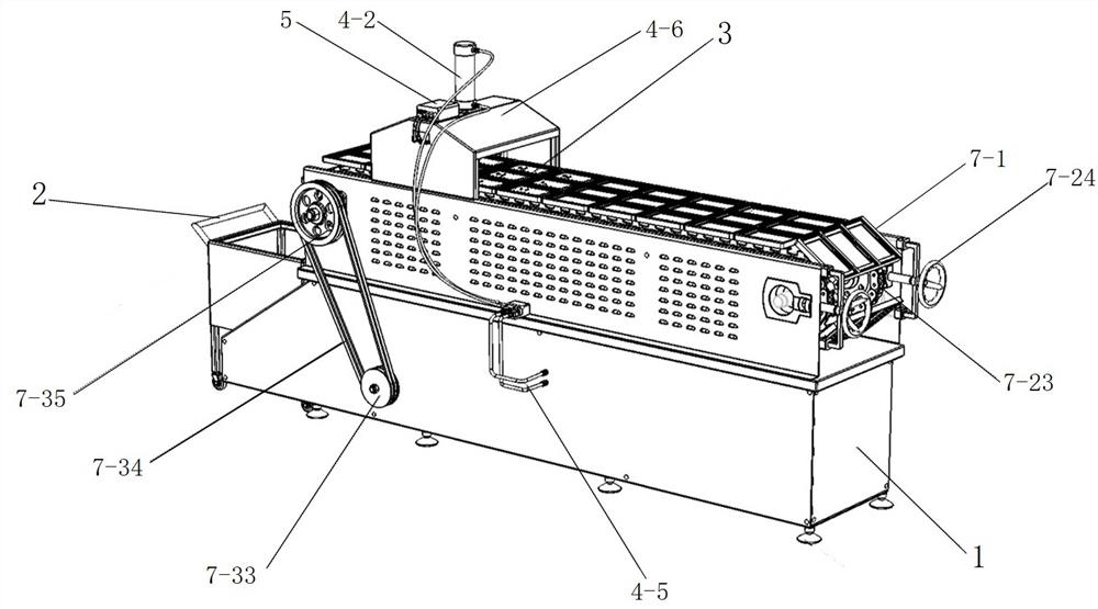
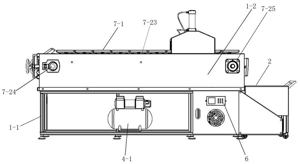
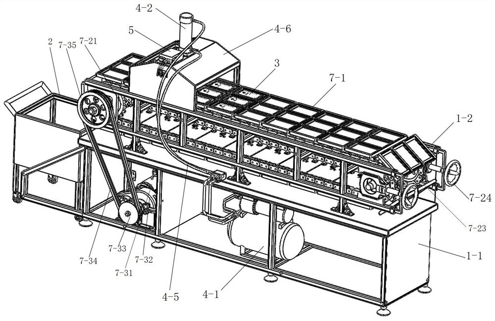
[0036] Such as Figure 1-9 As shown, an automatic non-destructive disassembly system for a waste mobile terminal of the present invention includes an active disassembly system, a frame 1, a belt transmission mechanism and a recovery mechanism 2, and the frame 1 includes a lower box 1-1 and an upper box 1-2, the bottom of the lower box 1-1 is equipped with lockable universal wheels or feet, the recovery mechanism 2 is a trolley, and the bottom of the trolley is equipped with lockable universal wheels, and the front end of the trolley is fixed on the lower box 1- 1, the active disassembly system includes air pump 4-1, cylinder 4-2, truss 4-3 and live contact 4-4, air pump 4-1 is installed in the lower box 1-1, and air pump 4-1 passes through the air pipe 4-5 is connected to the cylinder 4-2, the controller 5 is installed on the outer bracket 4-6, and is used to adjust the output gas flow rate of the air pump 4-1, and the gas flow meter 6 is installed on the side of the lower box...
Embodiment 2
[0042] The difference between this embodiment and Embodiment 1 is that the number of driving gear 7-21 is one, the number of driven gear 7-22 and ring rack 7-23 is consistent with driving gear 7-21, and the number of driving gear 7-21 is consistent with that of driving gear 7-21. 21 is connected on the large crawler wheel 7-35 by a shaft, and is located in the middle of the upper box body 1-2, the upper box body 1-2 front is fixed on the bearing seat 7-25 by the fixed rod 7-24, the bearing seat Rotating shaft is installed on 7-25, and driven gear 7-22 is installed on the rotating shaft, and is positioned at driving gear 7-21 right ahead, and ring rack 7-23 meshes and is connected in driving gear 7-21 and driven gear 7-22 Outer side; conveyor belt 7-1 comprises several groove plates 7-11, each groove plate 7-11 is fixed in series on the outer side of ring rack 7-23 by locking piece, groove plate 7-11 is fixed by 2~ Composed of 4 grooved plates of different sizes, each grooved p...
PUM
 Abstract
Description
Claims
Application Information
 - R&D
- Intellectual Property
- Life Sciences
- Materials
- Tech Scout
- Unparalleled Data Quality
- Higher Quality Content
- 60% Fewer Hallucinations
Browse by: Latest US Patents, China's latest patents, Technical Efficacy Thesaurus, Application Domain, Technology Topic, Popular Technical Reports.
© 2025 PatSnap. All rights reserved.Legal|Privacy policy|Modern Slavery Act Transparency Statement|Sitemap|About US| Contact US: help@patsnap.com


