Slitting equipment for thin plate

A sheet and equipment technology, applied in the field of thin sheet cutting equipment, can solve problems such as low processing efficiency, and achieve the effect of convenient maintenance and disassembly

Pending Publication Date: 2020-09-25
嘉善永升五金厂
View PDF5 Cites 2 Cited by
  • Summary
  • Abstract
  • Description
  • Claims
  • Application Information

AI Technical Summary

Problems solved by technology

[0004] When processing metal packing buckles, the metal sheet needs to be cut first,

Method used


Image

  • Slitting equipment for thin plate
  • Slitting equipment for thin plate
  • Slitting equipment for thin plate

Examples


Embodiment Construction

[0038] The technical solution of this patent will be further described in detail below in conjunction with specific embodiments.

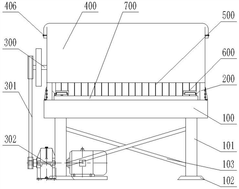
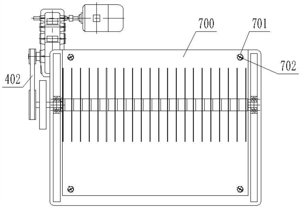
[0039] see Figure 1-10 , a cutting device for thin plates, including a base 100, a table 700, a shell 400 and a pressing device 600,

[0040] The four corners of the base 100 are provided with supporting legs 101, wherein the supporting legs 101 are fixedly connected with lacing bars 103 arranged obliquely to improve the strength of the structure, and the bottom of the supporting legs 101 is fixedly provided with supporting feet 102, and the supporting feet 102 are truncated cone,

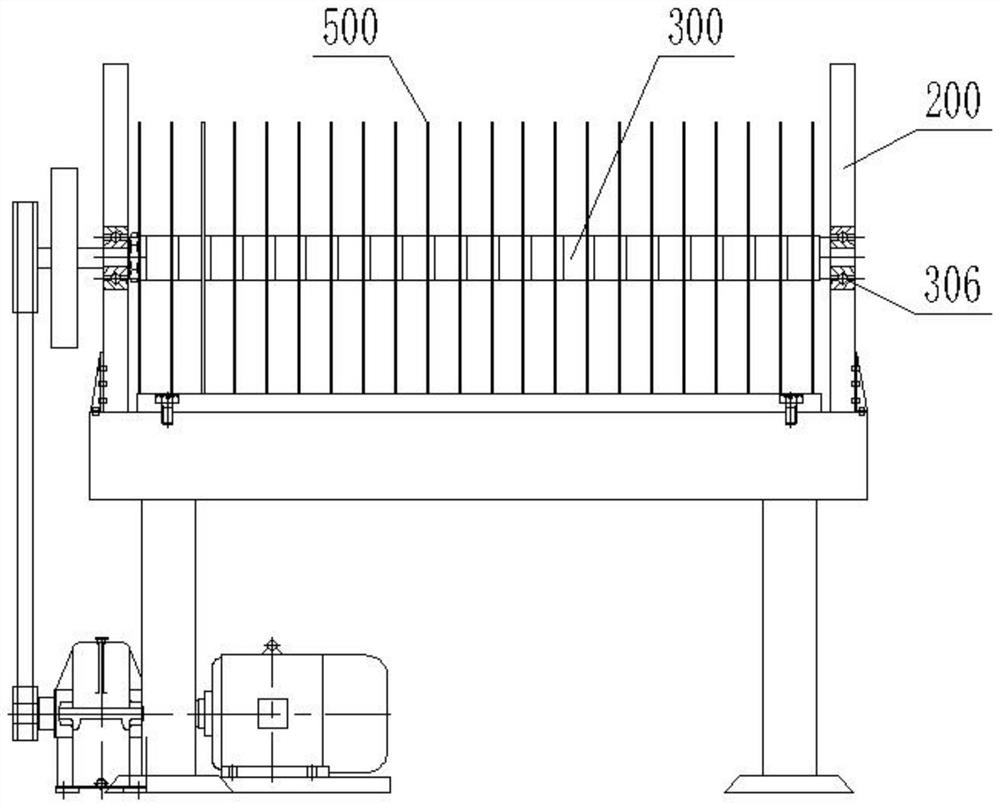
[0041] The left and right sides of the top of the base 100 are symmetrically provided with support plates 200, and a cutting shaft 300 is arranged between the support plates 200. Both ends of the cutting shaft 300 are connected to the support plate 200 through first bearings 306 for rotation, wherein the cutting shaft The left end of 300 passes support plate 200,

...


PUM


Abstract

The invention discloses slitting equipment for a thin plate. The slitting equipment for the thin plate comprises a base, a table top, a shell cover and a plate pressing device, wherein supporting plates are symmetrically arranged on the left side and the right side of the top of the base, cutting shafts are arranged between the supporting plates, the two ends of the cutting shafts are rotationallyconnected to the supporting plates through first bearings, the left ends of the cutting shafts penetrate out of the supporting plates, the left end parts of the cutting shafts are in transmission connection with power equipment through a belt transmission mechanism, cutting blades are fixedly mounted on the cutting shafts in a sleeve manner, the shell cover is erected at the tops of the supporting plates, the table top is located between the two supporting plates, the table top is fixedly installed on the base, and the plate pressing device is located on the inner sides of the supporting plates and comprises a sliding rail and a sliding block. According to the slitting equipment, when the slitting equipment works, a worker pushes the plate from the front end of the equipment, a power mechanism drives the cutting shafts to rotate through the belt transmission mechanism, the cutting shafts rotate, and the plate enters the space between the cutting blades on the two cutting shafts to becut.

Description

technical field [0001] The invention relates to a food processing equipment, in particular to a cutting equipment for thin plates. Background technique [0002] The packing buckle is a product made by using the packing buckle to fix the joints when using the packing belt to make the packing belt stronger. Packing buckles are classified according to different materials: plastic packing buckles, plastic steel packing buckles and iron packing buckles. [0003] The iron packing buckle is made of special strip steel and special tinplate, and there are dense thorns in the packing steel mouth, which can prevent slipping, increase the tension of the joint, and ensure the safety of the goods. The surface of the packing steel buckle is galvanized to prevent rust. The specifications are between 13-19mm in width and 0.6-1.0mm in thickness, and can be matched according to the specifications of the packing belt. Ordinary iron packing buckles are made of waste cans Lulu slices and eight...

Claims


Application Information

Patent Timeline
IPC IPC(8): B23D19/06B23Q3/06
CPCB23D19/06B23Q3/064
Inventor 王永芳
Owner 嘉善永升五金厂
Why Eureka
Try Eureka