
Polishing device and method for plated piston rod assembly

A processing equipment and piston rod technology, which is applied in metal processing equipment, grinding/polishing equipment, surface polishing machine tools, etc., can solve the problems that affect the polishing efficiency of piston rod components, and the polishing cannot be carried out continuously, so as to improve the polishing work efficiency , Convenient polishing operation, improve the effect of polishing stability

Active Publication Date: 2020-09-25
青岛艺天成精密机械有限公司
View PDF10 Cites 1 Cited by
  • Summary
  • Abstract
  • Description
  • Claims
  • Application Information

AI Technical Summary

Problems solved by technology

[0004] To this end, the embodiment of the present invention provides a polishing processing equipment and processing method of a plated piston rod assembly. The polishing wheel is driven by the rotation of the polishing disc to polish the piston rod assembly. The positioning piece is used for inductive detection, and the automatic brake is used to hold and brake the drive shaft, and the rotation state of the polishing disc is positioned and fixed, which is convenient for continuous polishing operations on both ends of the conveyed piston rod assembly at the same time, without the need for piston rod assembly Perform a U-turn operation to improve the polishing work efficiency to solve the problem in the prior art that after one end of the piston rod assembly is polished, the piston rod assembly needs to be turned around to polish the other end, and the polishing of the piston rod assembly cannot be carried out continuously, which affects the piston rod assembly polishing efficiency, resulting in problems

Method used


Image

  • Polishing device and method for plated piston rod assembly
  • Polishing device and method for plated piston rod assembly
  • Polishing device and method for plated piston rod assembly

Examples


Embodiment Construction

[0036] The implementation mode of the present invention is illustrated by specific specific examples below, and those who are familiar with this technology can easily understand other advantages and effects of the present invention from the contents disclosed in this description. Obviously, the described embodiments are a part of the present invention. , but not all examples. Based on the embodiments of the present invention, all other embodiments obtained by persons of ordinary skill in the art without making creative efforts belong to the protection scope of the present invention.

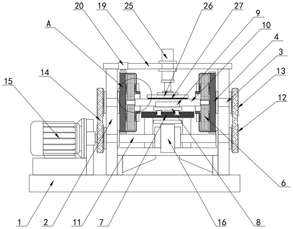
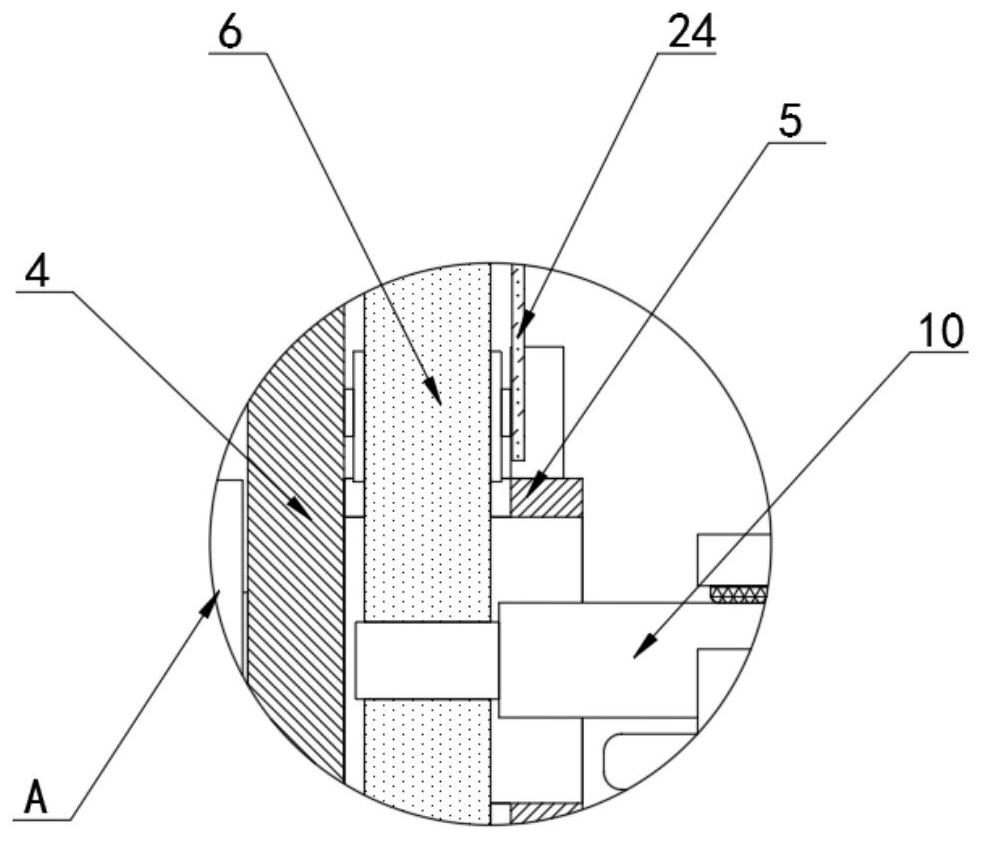
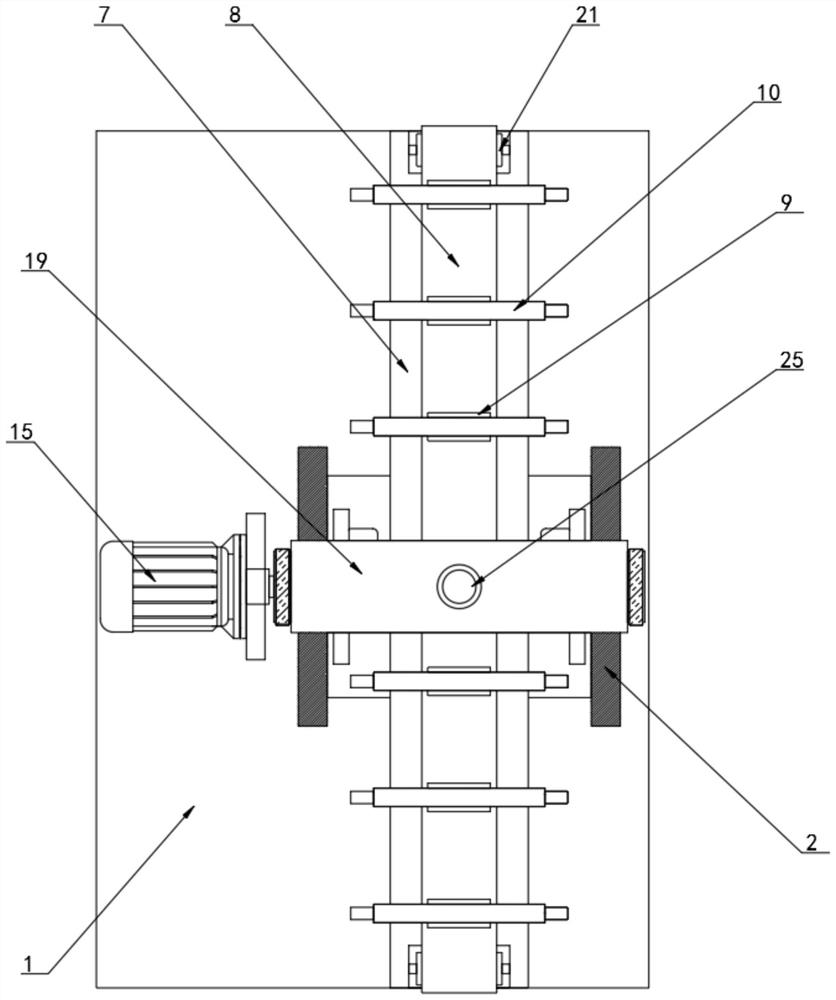
[0037] Refer to the attached Figure 1-7 , the polishing processing equipment of a kind of post-plated piston rod assembly of this embodiment, comprises equipment base 1, and the top of described equipment base 1 is provided with equipment frame 2, and both ends of the top of described equipment frame 2 are fixedly provided with rotating shaft 3. A polishing disc 4 is fixedly arranged at one end...


PUM


Abstract

The invention discloses a polishing device and method for a plated piston rod assembly, and particularly relates to the technical field of polishing devices. The device comprises a device base. A device rack is arranged at the top of the device base. The two ends of the top of the device rack are each fixedly provided with a rotating shaft. A polishing disc is fixedly arranged at one end of each of the two rotating shafts. A fixing sleeve is fixedly arranged in the middle of each polishing disc. The top and the bottom of each fixing sleeve are each provided with a polishing grinding wheel. Theaxles of the polishing grinding wheels are fixedly connected with the polishing discs. The polishing discs rotate to drive the polishing grinding wheels to polish and grind the piston rod assembly. An infrared sensor performs induction detection on a first positioning piece and a second positioning piece. In cooperation with an automatic holding brake, the drive shaft is held and braked, the rotating states of the polishing discs are positioned and fixed, continuous polishing operation is performed on the two ends of the piston rod assembly conveniently, and the polishing efficiency is improved.

Description

technical field [0001] The invention relates to the technical field of polishing equipment, in particular to a polishing processing equipment for a plated piston rod assembly and a processing method thereof. Background technique [0002] The piston rod is a connecting part that supports the piston to do work. Most of it is used in the cylinder and cylinder motion executive parts. It is a moving part with frequent movements and high technical requirements. The piston rod assembly is then chrome-plated and polished on the surface of the piston rod assembly. After polishing, the polishing quality needs to be tested to avoid surface defects. [0003] The prior art has the following deficiencies: the existing polishing and testing production line of the piston rod assembly is a linear layout, and the piston rod assembly on the working line is moved by a conveyor belt, but the general polishing method is to first polish one end of the piston rod assembly. The first step of polish...

Claims


Application Information

Patent Timeline
Patent Type & Authority Applications(China)
IPC IPC(8): B24B1/00B24B29/04B24B41/00B24B41/02B24B41/06B24B47/12B24B49/12B24B55/00
CPCB24B29/04B24B41/005B24B47/12B24B49/12B24B55/00B24B41/067B24B41/02B24B1/00
Inventor 梁慧张成坤
Owner 青岛艺天成精密机械有限公司
Learn More