Automatic noodle cutting device

An automatic cutting device and noodle technology, applied in metal processing, etc., can solve the problems of reduced work efficiency, effort, easy soreness, etc., and achieve the effect of high work efficiency

Active Publication Date: 2020-09-25
恩施沈氏食品有限公司
View PDF8 Cites 1 Cited by
  • Summary
  • Abstract
  • Description
  • Claims
  • Application Information

AI Technical Summary

Problems solved by technology

[0004] In order to overcome the disadvantages that people need to manually cut the dough into noodles, it takes a long time, it is laborious, and the hand is easy to be sore, which leads to the shortcoming of the subsequent work efficiency. Labor-saving and efficient automatic noodle cutting device

Method used


Image

  • Automatic noodle cutting device
  • Automatic noodle cutting device
  • Automatic noodle cutting device

Examples


Embodiment 1

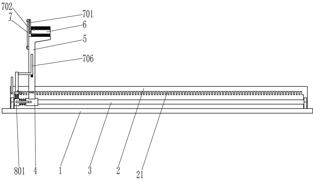
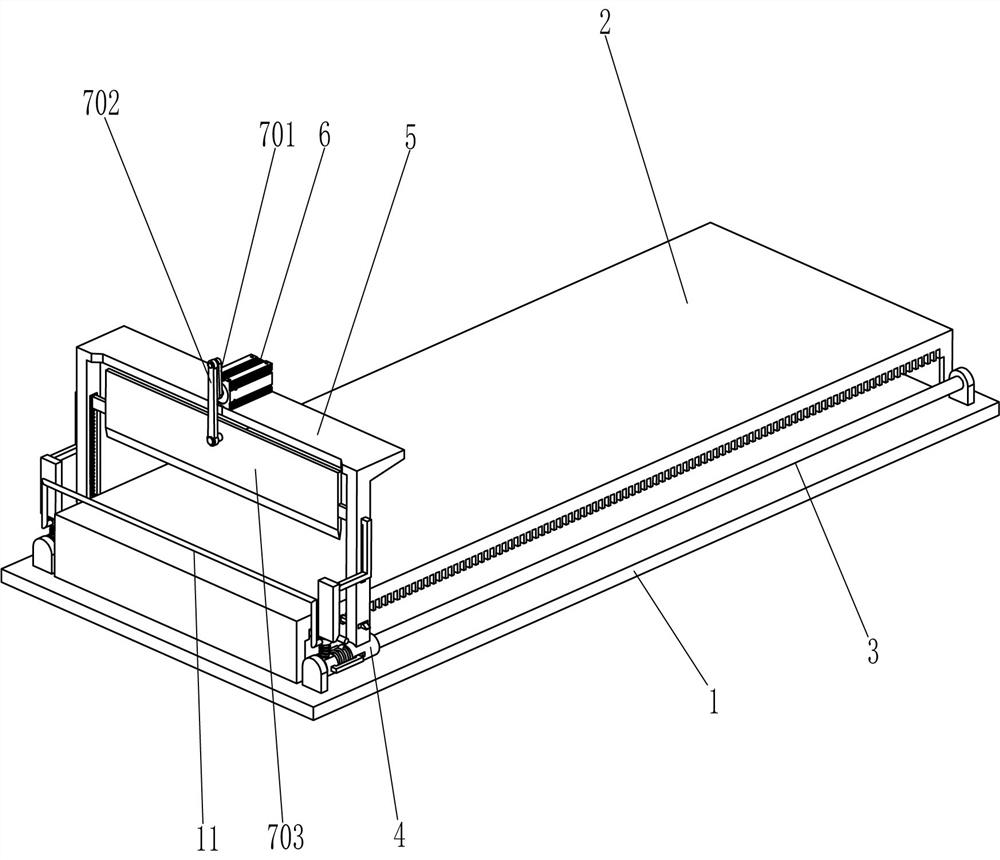
[0021] An automatic noodle cutting device, such as Figure 1-3 As shown, it includes a bottom plate 1, a placement plate 2, a guide rod 3, a first sliding sleeve 4, an n-type plate 5, a servo motor 6, a cutting assembly 7 and a moving assembly 8. A placement plate 2 is fixed at the top and middle of the bottom plate 1, There are grooves 21 evenly spaced on the front and back sides of the top of the placement plate 2. The guide rods 3 are fixed on the middle of the front and back sides of the top of the bottom plate 1. The guide rods 3 are located on the front and rear sides of the placement plate 2, and the guide rods 3 slide on The first sliding sleeve 4 is provided with a first sliding sleeve 4, the front and rear sides of the first sliding sleeve 4 are provided with grooves on the left side, and an n-type plate 5 is fixedly connected between the outer tops of the first sliding sleeve 4 on the front and rear sides. A servo motor 6 is installed in the middle of the top by bolt...

Embodiment 2

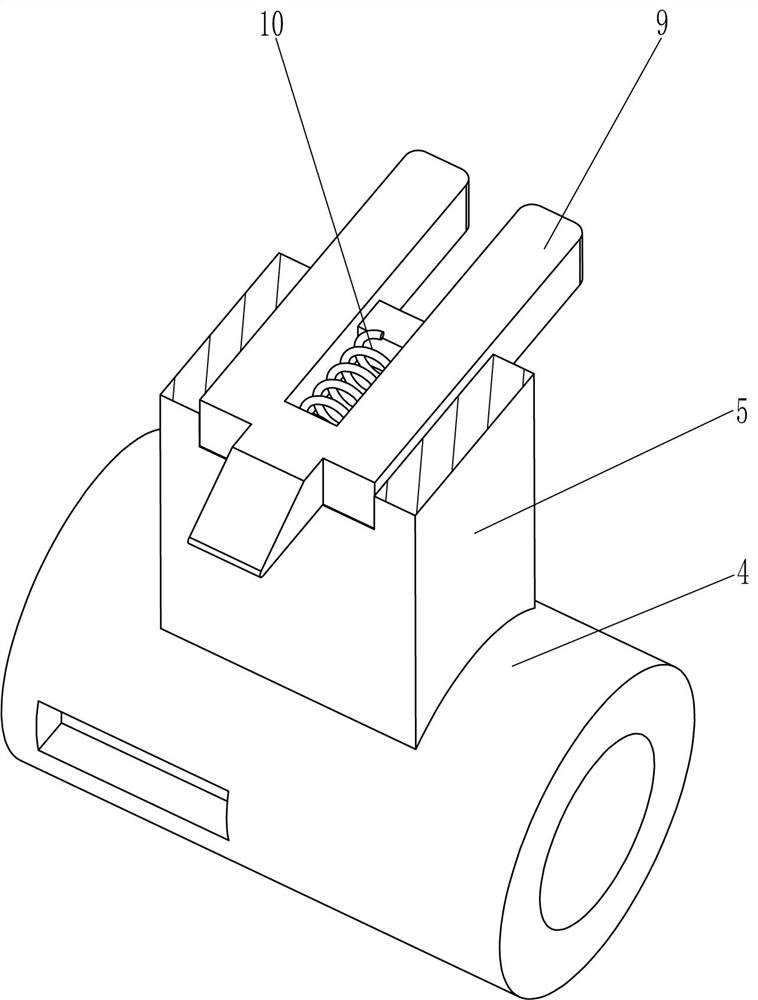
[0028] On the basis of Example 1, such as image 3 with Figure 4 As shown, it also includes a clamping block 9 and a fourth spring 10. The lower parts of the front and rear sides of the n-type plate 5 are slidably connected to the clamping block 9, the clamping block 9 is located under the slider 704, the clamping block 9 and the contact frame 706 In cooperation, the clamping block 9 also cooperates with the groove 21, the inner front surface of the front clamping block 9 and the front inner front of the n-type plate 5 are connected with a fourth spring 10, and the inner and rear surfaces of the rear clamping block 9 are connected to the rear of the n-type plate 5. A fourth spring 10 is also connected between the inner sides.

[0029] When the contact frame 706 is in contact with the contact rod 807, the contact frame 706 is also in contact with the clamping block 9. The contact frame 706 also drives the clamping block 9 to move inward, the fourth spring 10 is compressed, and the...


PUM


Abstract

The invention relates to a cutting device, in particular to an automatic noodle cutting device. According to the technical problem, the automatic noodle cutting device which can replace manual work tocut dough into noodles, saves labor and is high in working efficiency is designed. The automatic noodle cutting device comprises a bottom plate and guide rods; one side of the bottom plate is fixedlyconnected with a placing plate, grooves are symmetrically formed in the inner side in the placing plate at intervals; and the guide rods are symmetrically and fixedly connected to one side of the bottom plate and located on the two sides of the placing plate. According to the automatic noodle cutting device, the dough is placed on the placing plate, a servo motor is started, then a cutter can move up and down to cut the dough into the noodles, and through the cooperation effect of a moving assembly, the cutter can move rightwards by a certain distance every time the cutter cuts the dough, sothat the dough is comprehensively cut into the noodles, the dough does not need to be manually cut into noodles by people, labor is saved, and the working efficiency is high.

Description

Technical field [0001] The invention relates to a cutting device, in particular to an automatic noodle cutting device. Background technique [0002] Noodles originated in China and have been made and eaten for more than four thousand years. Noodles are a kind of healthy food that is simple to make, easy to eat, and rich in nutrition. It can be a staple food and fast food. It has long been accepted and loved by people all over the world. Noodles are made of grains or legumes flour and water to grind into dough, then press or roll or stretch into slices and then cut or press, or use means such as rubbing, pulling, kneading, etc., into strips or small pieces, and finally A kind of food that is cooked, fried, braised and fried. There are many patterns and varieties. In the process of making noodles, dough is made by fermentation of flour, and then the dough is cut into noodles. [0003] Existing cutting devices, such as the Chinese patent with patent publication number CN109807967A,...

Claims


Application Information

Patent Timeline
IPC IPC(8): B26D1/08B26D5/08B26D5/06B26D7/20B26D7/00
CPCB26D1/08B26D5/086B26D5/06B26D7/20B26D7/00B26D2210/02
Inventor 刘小军
Owner 恩施沈氏食品有限公司
Why Eureka
Try Eureka