Barrel-shaped workpiece taking-out jig

A workpiece and jig technology, which is applied in the field of barrel-shaped workpiece removal jigs, can solve the problems of heavy jig weight, high failure rate, and many fixing parts, and achieve the goal of reducing jig cost, maintenance difficulty, and failure rate Effect

Pending Publication Date: 2020-09-25
伯朗特机器人股份有限公司
View PDF0 Cites 0 Cited by
  • Summary
  • Abstract
  • Description
  • Claims
  • Application Information

AI Technical Summary

Problems solved by technology

[0002] At present, the connecting rod type removal jig for barrel-shaped workpieces is mainly used to take out the barrel-shaped workpiece products in the inner die of the injection molding machine. The existing removal jig uses the cylinder to control the suction cup to fit the inner surface of the barrel-shaped workpiece to achieve suction. Because one cylinder controls one suction cup in the existing jig, there are many cylinders and many fixing parts, which leads to heavy weight and high cost of the jig. At the same time, due to the large number of cylinders, the failure rate may also increase accordingly.

Method used


Image

  • Barrel-shaped workpiece taking-out jig
  • Barrel-shaped workpiece taking-out jig
  • Barrel-shaped workpiece taking-out jig

Examples


Embodiment Construction

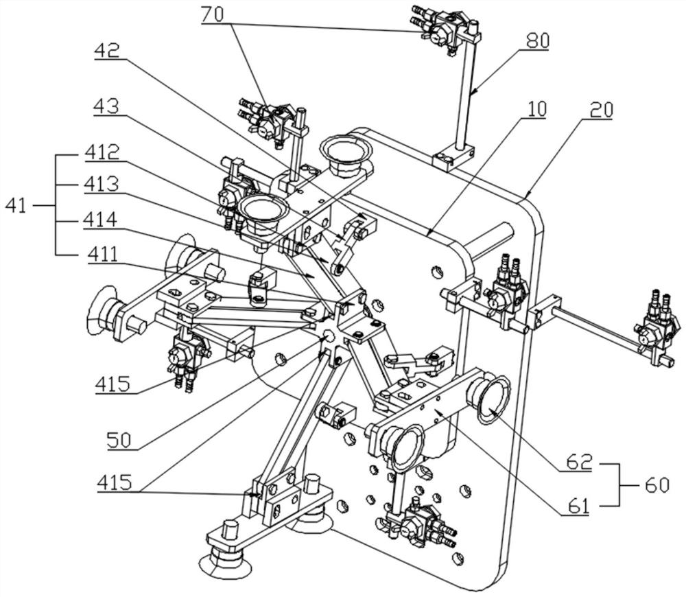
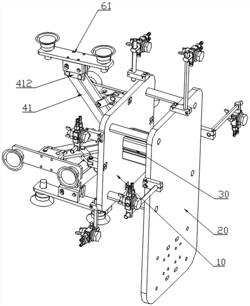
[0029] see Figure 1 to Figure 4 , a barrel-shaped workpiece removal jig of the present embodiment, including a jig plate 10, a fixed mounting plate 20, a drive source 30, four sets of linkage mechanisms, connectors 50, four sets of suction cup sets 60, and a number of release agent nozzles 70;

[0030] Specifically, the fixture plate 10 is installed on the fixed mounting plate 20, and the fixed mounting plate 20 can be installed and connected with an external manipulator (not shown in the figure); the driving source 30 is arranged on the fixture plate 10 In this embodiment, the driving source 30 is preferably a cylinder; the connecting member 50 is arranged on the output shaft of the driving source 30;

[0031] Specifically, each group of linkages includes a set of parallelogram linkages 41, fixed rods 42 and movable rods 43;

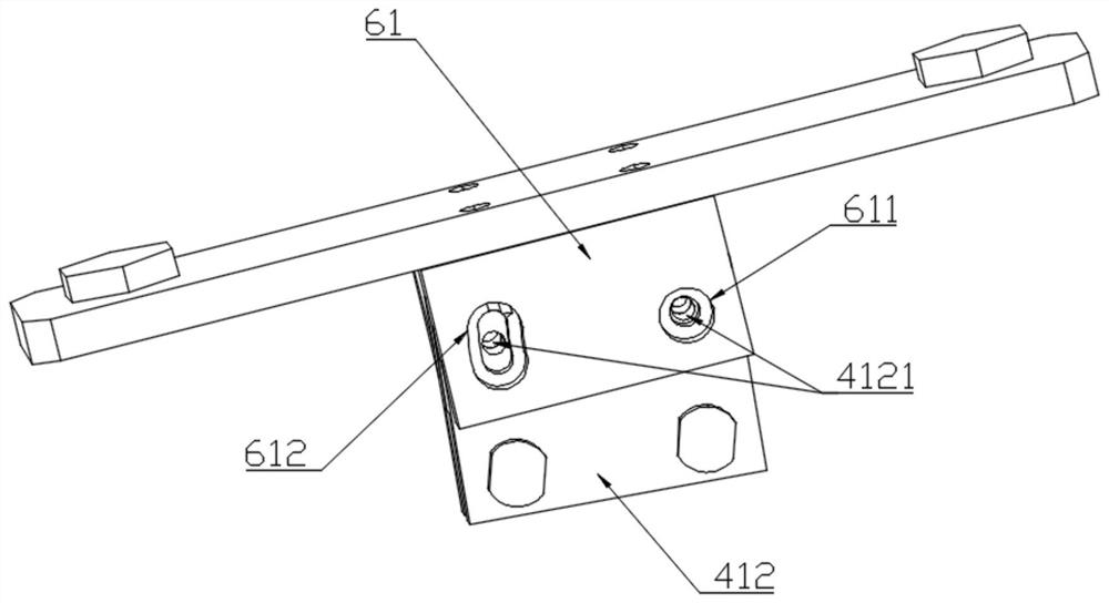
[0032] The parallelogram linkage mechanism 41 includes a first connecting rod 411, a second connecting rod 412, a third connecting rod 413 and a fou...


PUM


Abstract

The invention relates to a barrel-shaped workpiece taking-out jig. The barrel-shaped workpiece taking-out jig comprises a jig plate, a driving source, at least two connecting rod mechanisms and suction cup sets with the same number as the connecting rod mechanisms, wherein each group of connecting rod mechanisms comprises a parallelogram connecting rod mechanism, each parallelogram connecting rodmechanism comprises a first connecting rod and a second connecting rod which are arranged in parallel, the first connecting rods are arranged at the output end of the driving source, the suction cup sets are arranged on the second connecting rods, the driving source drives the first connecting rods to do feeding motion along the axes of the first connecting rods so as to drive the corresponding connecting rod mechanisms to do rotating motion, and rotating working faces of the connecting rod mechanism are parallel to the axes of the first connecting rods. According to the barrel-shaped workpiece taking-out jig, only one driving source is adopted, the failure rate of a machine is greatly reduced, and the maintenance difficulty and cost are reduced.

Description

technical field [0001] The invention relates to the technical field of tooling and jigs, in particular to a jig for taking out barrel-shaped workpieces. Background technique [0002] At present, the connecting rod type removal jig for barrel-shaped workpieces is mainly used to take out the barrel-shaped workpiece products in the inner die of the injection molding machine. The existing removal jig uses the cylinder to control the suction cup to fit the inner surface of the barrel-shaped workpiece to achieve suction. Because one cylinder controls one suction cup in the existing jig, the number of cylinders is large and the number of fixing parts is also large, which leads to heavy weight and high cost of the jig. At the same time, due to the large number of cylinders, the failure rate may also increase accordingly. [0003] Therefore, it is necessary to provide a novel barrel-shaped workpiece removal jig. Contents of the invention [0004] Based on this, the object of the p...

Claims


Application Information

Patent Timeline
Patent Type & Authority Applications(China)
IPC IPC(8): B29C45/43B29C33/58B29L22/00
CPCB29C33/58B29C45/43B29L2031/7154
Inventor 洪宏彬
Owner 伯朗特机器人股份有限公司
Why Eureka
Try Eureka