Municipal bridge with reinforcing devices

A reinforcement device, municipal technology, applied in the direction of erecting/assembling bridges, bridges, bridge parts, etc., can solve the problems of low mechanical strength and bridge collapse, and achieve the goal of reducing traffic accidents, increasing structural strength, and reducing the probability of collapse. Effect

Pending Publication Date: 2020-09-25
浙江立信建设集团有限公司
View PDF0 Cites 2 Cited by
  • Summary
  • Abstract
  • Description
  • Claims
  • Application Information

AI Technical Summary

Problems solved by technology

[0004] The above existing technical solutions have the following defects: the existing bridge body is supported by a single support column in the middle, and the strength of the mechanisms on both sides of the brid...

Method used


Image

  • Municipal bridge with reinforcing devices
  • Municipal bridge with reinforcing devices
  • Municipal bridge with reinforcing devices

Examples


Embodiment 1

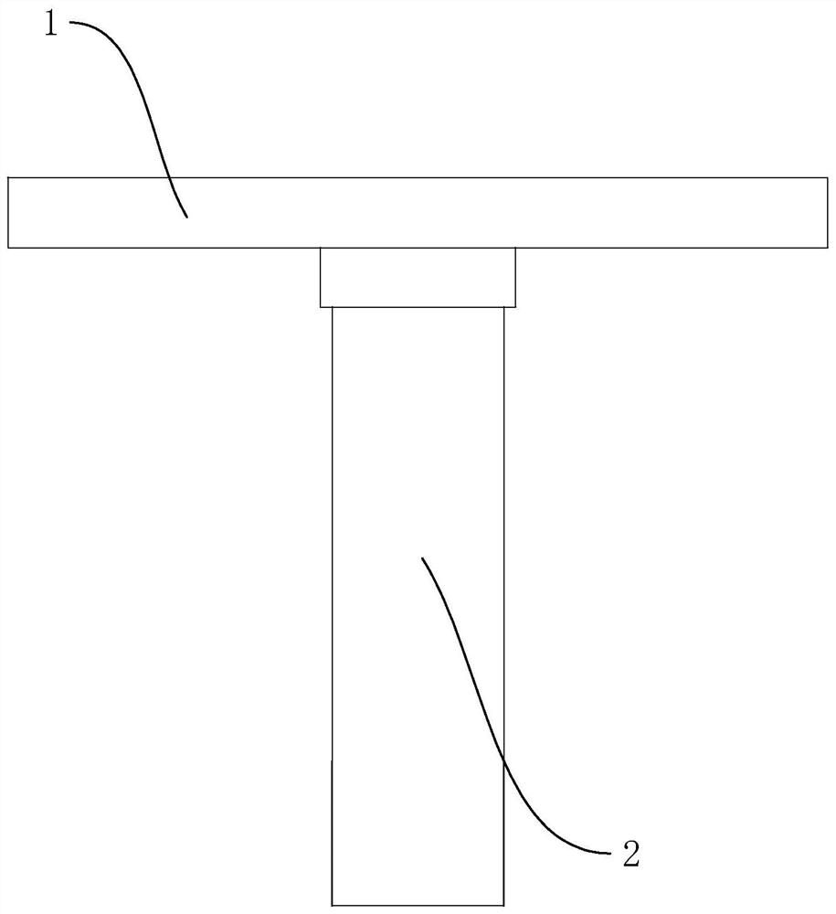
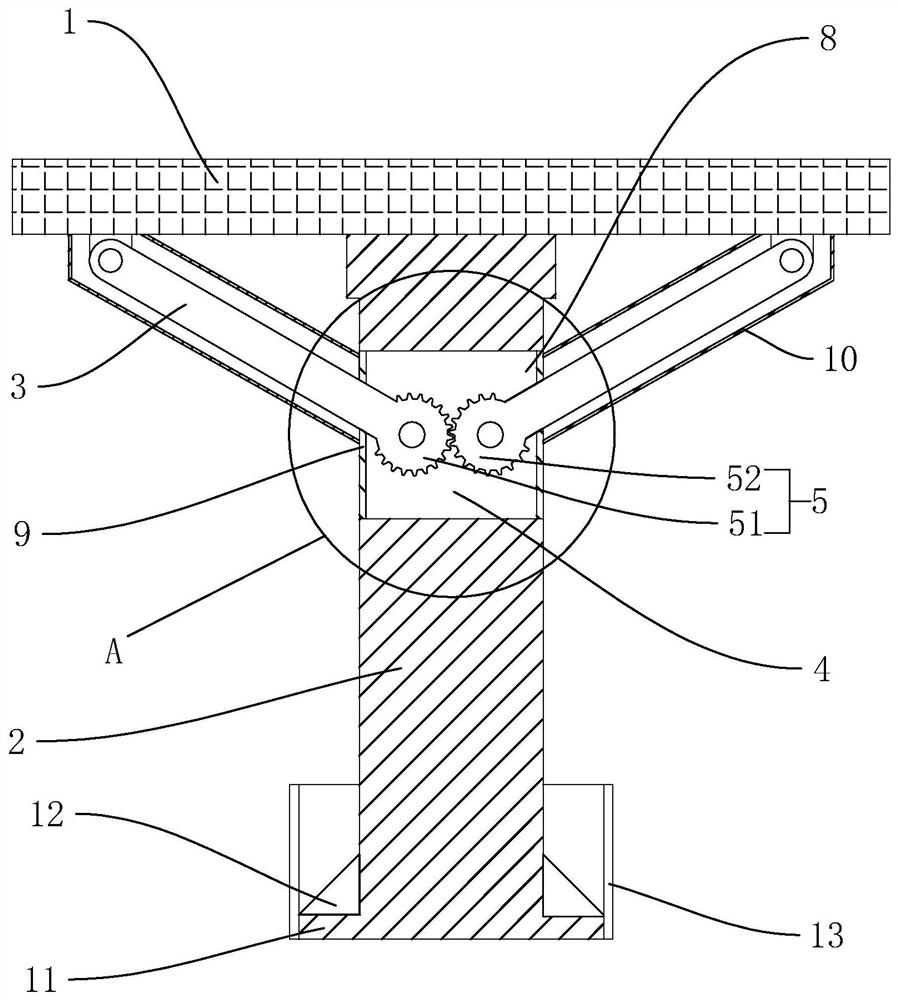
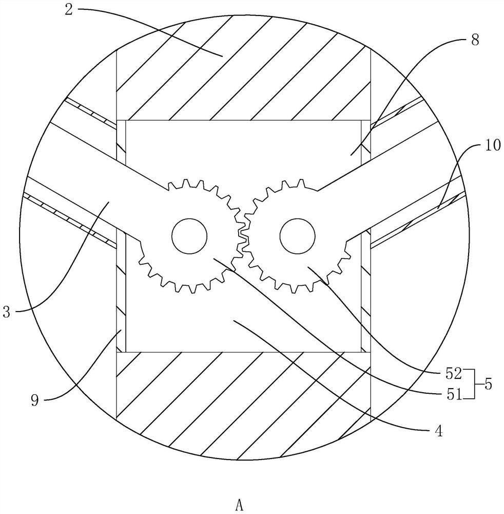
[0038] refer to figure 2 , is a kind of municipal bridge with a reinforcement device disclosed by the present invention, comprising a bridge body 1 and a support column 2 fixedly installed at the bottom of the bridge body 1, and the end of the support column 2 away from the bridge body 1 is fixed on the ground, and the bridge body 1 and The supporting columns 2 are all made of reinforced concrete. The supporting columns 2 are provided with reinforcing rods 3 on both sides of the bridge body 1 in the width direction. The reinforcing rods 3 are preferably reinforced rods. Hinged in the placement groove 4, the other end is hinged at the bottom of the bridge body 1, a linkage assembly 5 is arranged in the placement groove 4, and the linkage assembly 5 links two reinforcement rods 3 to rotate in reverse; the reinforcement rod 3 has a reinforcing effect on the bridge body 1, At the same time, when the force on one side of the bridge body 1 is too large and collapses, the reinforcin...

Embodiment 2

[0044] A municipal bridge with reinforcing devices, the difference between the second embodiment and the first embodiment is that the linkage assembly 5 of the second embodiment is different from the first embodiment.

[0045] refer to Figure 4 and Figure 5 , the linkage assembly 5 includes a first link 53 fixed on one of the reinforcing bars 3 and a second link 54 fixed on the other reinforcing bar 3, the first link 53 and the second link 54 The reinforcement rod 3 that is all fixedly arranged on it is hinged on the side of the bridge body 1 away from the supporting column 2, and the second connecting rod 54 has two that are respectively arranged on both sides of the first connecting rod 53 in the width direction, and the second connecting rod 54 A horizontal waist-shaped groove 6 is provided on the rod 54, and hinged rods 7 are fixed on both sides of the first connecting rod 53. The hinged rod 7 rotates and slides in the waist-shaped groove 6. The same direction of rotat...


PUM


Abstract

The invention relates to the technical field of municipal buildings, especially to a municipal bridge with reinforcing devices. The bridge comprises a bridge body and supporting columns fixedly installed at the bottom of the bridge body. The ends, away from the bridge body, of the supporting columns are fixedly arranged on the ground. Reinforcing rods are arranged on the two sides, in the width direction of the bridge body, of the supporting column;a containing groove is formed in the supporting column, one end of each reinforcing rod is hinged into the containing groove, the other end of eachreinforcing rod is hinged to the bottom of the bridge body, a linkage assembly is arranged in each containing groove, and the linkage assembly is in linkage with the two reinforcing rods to rotate reversely. The bridge has the effects that the two sides of the bridge body in the width direction can be reinforced, the collapse probability of the bridge body is reduced, and traffic accidents are reduced.

Description

technical field [0001] The invention relates to the technical field of municipal buildings, in particular to a municipal bridge with a reinforcing device. Background technique [0002] Viaduct is a kind of municipal bridge, which generally refers to bridges that cross deep ditches and canyons instead of high embankments, and bridges that span roads in urban bridges; the construction of viaducts can divert urban traffic and slow down urban traffic congestion. [0003] Existing viaducts (such as figure 1 shown) includes a bridge body 1 and a support column 2 fixedly installed at the bottom of the bridge body 1. The end of the support column 2 away from the bridge body 1 is fixed on the ground; since the existence of the support column 2 will affect the road below, the Some support columns 2 usually adopt a single support column 2 set up in the middle of the bridge body 1, and the single support column 2 can reduce the impact on the road surface below the bridge body 1. [00...

Claims


Application Information

Patent Timeline
IPC IPC(8): E01D22/00E01D19/00E01D19/02
CPCE01D19/00E01D19/02E01D22/00
Inventor 陈玉飞诸国强谭渭枫姚富洪吴琼张纬黄建飞王旗姚佳宇谭松坤
Owner 浙江立信建设集团有限公司
Why Eureka
Try Eureka