A Radial Sealing System Fitting Contact Air Preheater

A technology of radial sealing and air preheater, which is applied in the direction of engine sealing, indirect carbon dioxide emission reduction, combustion method, etc. Influence, reduce radial air leakage, improve unit efficiency and the effect of economical operation level of equipment

Active Publication Date: 2022-05-27
DATANG BINZHOU POWER GENERATION CO LTD
View PDF9 Cites 0 Cited by
  • Summary
  • Abstract
  • Description
  • Claims
  • Application Information

AI Technical Summary

Problems solved by technology

[0007] The purpose of the present invention is to overcome the problem that the air preheater radial air leakage increases due to the increase of the sealing gap of the existing air preheater seal under full load, and provides a radial sealing system for the contact type air preheater, through the The mutual fit of the lower sealing surface enables the air preheater to be effectively compensated for the sealing gap in the mushroom-shaped deformation state, which can reduce the radial air leakage of the air preheater and improve the unit efficiency and the economical operation level of the equipment

Method used


Image

  • A Radial Sealing System Fitting Contact Air Preheater
  • A Radial Sealing System Fitting Contact Air Preheater
  • A Radial Sealing System Fitting Contact Air Preheater

Examples


Embodiment 1

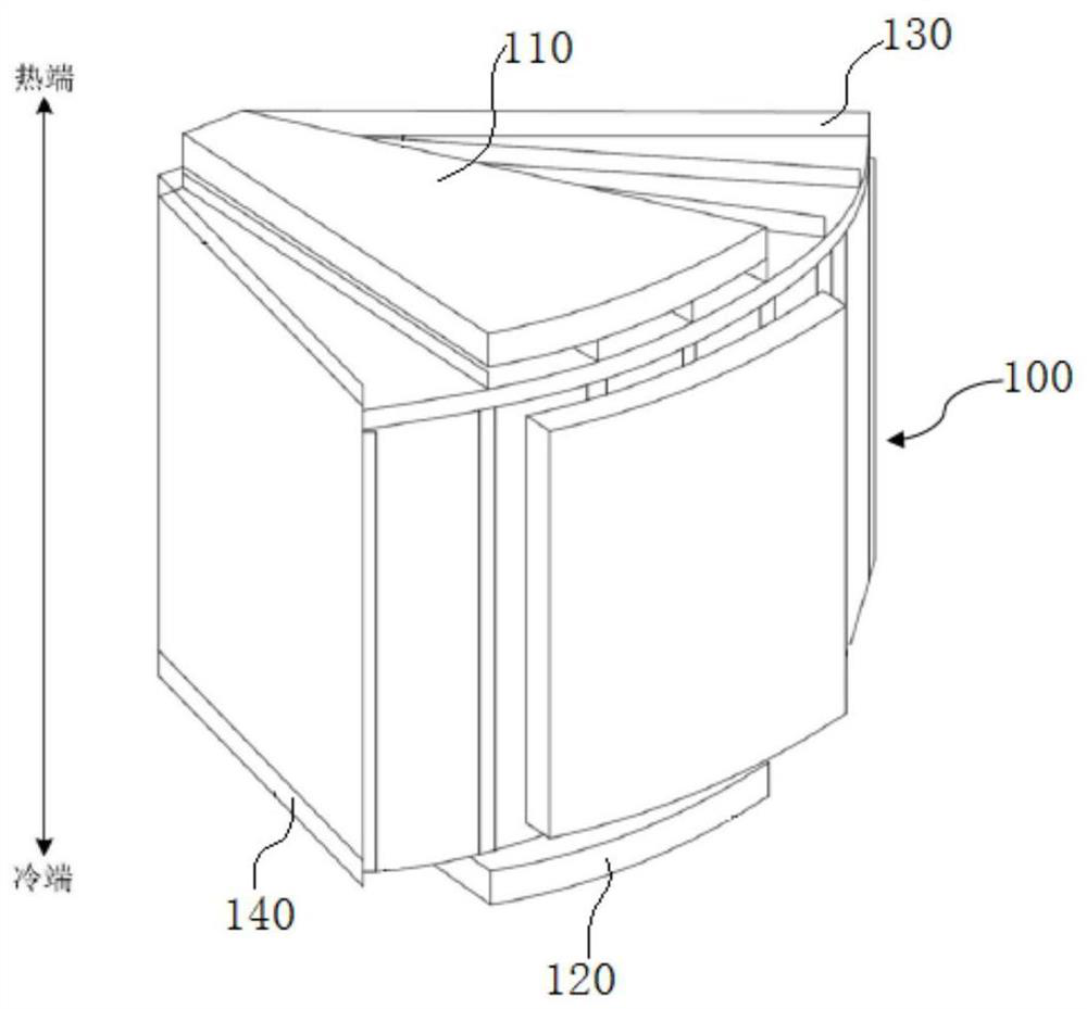
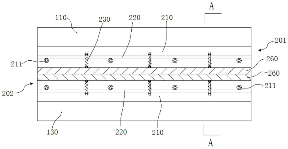
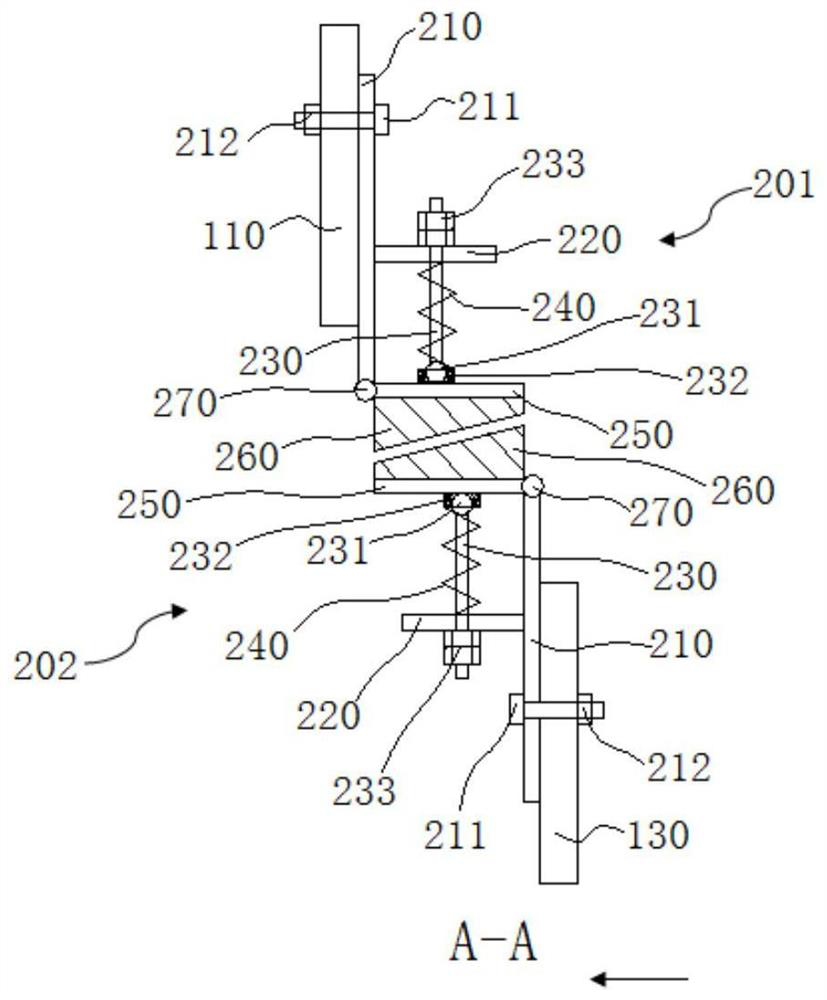
[0037] combine Figure 1-Figure 3 , a radial sealing system of a fitted contact type air preheater in this embodiment includes a radial sealing device 200 arranged between the hot end sector sealing plate 110 and the hot end radial partition plate 130 of the rotor 100. The radial sealing device 200 includes an upper sealing unit 201 arranged at the lower part of the hot end fan-shaped sealing plate 110 and a lower sealing unit 202 arranged at the lower part of the hot end radial partition plate 130. The upper sealing unit 201 and the lower sealing unit 202 have the same structure and are symmetrically distributed , the bottom of the upper sealing unit 201 and the top of the lower sealing unit 202 form a mutual fit, and are sealed in pairs, so that the sealing gap of the air preheater can be effectively compensated under the mushroom-shaped deformation state, so as to ensure that the air preheater is still under full load operation. It can ensure a good sealing effect, effectiv...

Embodiment 2

[0043] The radial sealing system of a contact-type air preheater in this embodiment is basically the same in structure as in Embodiment 1. Further, this embodiment also includes a fan-shaped sealing plate 120 disposed on the cold end of the rotor 100 and a diameter of the cold end. The radial sealing device 200 between the partition plates 140 is the same in structure as the radial sealing device 200 disposed between the hot end sector sealing plate 110 and the hot end radial partition plate 130 of the rotor 100, which not only ensures the hot end sector The sealing effect of the sealing plate 110 can also improve the sealing effect of the fan-shaped sealing plate 120 at the cold end of the air preheater, further reducing the air leakage rate of the air preheater, improving the efficiency of the boiler, and reducing the production cost.

[0044] In this embodiment, the hot-end fan-shaped sealing plate 110 and the fixing plate 210 are provided with connecting holes at the corres...


PUM


Abstract

The invention discloses a contact-type air preheater radial sealing system, which belongs to the technical field of air preheater sealing devices. The present invention includes a radial sealing device arranged between the fan-shaped sealing plate at the hot end and the radial partition at the hot end, the radial sealing device includes an upper sealing unit and a lower sealing unit, and the upper sealing unit and the lower sealing unit have the same structure, wherein The upper sealing unit includes a fixed plate arranged at the lower part of the fan-shaped sealing plate at the hot end. The bottom of one end of the fixed plate is hingedly provided with a friction block base, and the top of the friction block base is provided with a return spring, and the top of the return spring is fixed on the fixed plate through a support plate. , a friction block is also arranged under the friction block base, and the sections of the upper friction block and the lower friction block are trapezoidal structures arranged symmetrically. The purpose of the present invention is to overcome the problem that the radial air leakage of the air preheater increases under the condition of full load of the existing air preheater seal, and the radial air leakage of the air preheater can be reduced by the mutual fitting of the upper and lower sealing surfaces.

Description

technical field [0001] The invention relates to the technical field of air preheater sealing devices, and more particularly, to a radial sealing system of a fitted contact type air preheater. Background technique [0002] At present, the radial seal of the air preheater is a fixed seal, that is, the maximum expansion amount of the air preheater rotor is estimated, the corresponding gap is reserved, and the gap is compensated by the expansion amount during the operation of the equipment. Since the expansion of the air preheater rotor varies with the load of the unit, and the fan-shaped plate of the air preheater is fixed, the sealing gap cannot be adjusted with the change of the load, so the air preheater can only be closed when the unit load reaches the maximum. in a minimal state. After this type of sealed air preheater is put into operation, the air leakage rate is relatively large, generally about 5.5%-7%, and the maximum can be greater than 9%. The effect is not obvious...

Claims


Application Information

Patent Timeline
Patent Type & Authority Patents(China)
IPC IPC(8): F16J15/16F23L15/00
CPCF16J15/16F23L15/00Y02E20/34
Inventor 王振市徐美召丁浩杜华峰杨建宇
Owner DATANG BINZHOU POWER GENERATION CO LTD
Why Eureka
Try Eureka