
Transfer printing plate, preparation method of to-be-cut panel and to-be-cut panel

A transfer printing plate and transfer printing technology, applied in the field of display equipment, can solve problems such as PI materials are easy to absorb water and GOA units cannot work normally.

Active Publication Date: 2020-09-25
BOE TECH GRP CO LTD +1
View PDF8 Cites 0 Cited by
  • Summary
  • Abstract
  • Description
  • Claims
  • Application Information

AI Technical Summary

Problems solved by technology

[0004] In view of the shortcomings of the existing methods, this application proposes a transfer plate, a preparation method of the panel to be cut and the panel to be cut to solve the problem that the PI material in the prior art will cover the R angle of two adjacent sub-display areas in the panel to be cut In the area between, in the subsequent process, the PI material is easy to absorb water, which leads to the technical problem that the GOA unit cannot work normally

Method used


Image

  • Transfer printing plate, preparation method of to-be-cut panel and to-be-cut panel
  • Transfer printing plate, preparation method of to-be-cut panel and to-be-cut panel
  • Transfer printing plate, preparation method of to-be-cut panel and to-be-cut panel

Examples


Embodiment Construction

[0030] The application is described in detail below, and examples of embodiments of the application are illustrated in the accompanying drawings, wherein the same or similar reference numerals refer to the same or similar components or components having the same or similar functions throughout. Also, detailed descriptions of known technologies are omitted if they are not necessary for illustrating features of the present application. The embodiments described below with reference to the accompanying drawings are exemplary and are only used to explain the present application, but not to be construed as a limitation on the present application.

[0031] It will be understood by those skilled in the art that, unless otherwise defined, all terms (including technical and scientific terms) used herein have the same meaning as commonly understood by one of ordinary skill in the art to which this application belongs. It should also be understood that terms, such as those defined in a g...


PUM


Abstract

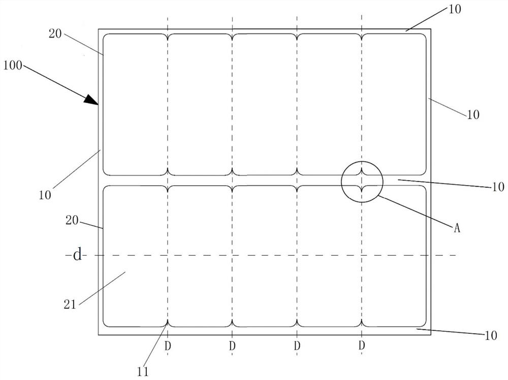
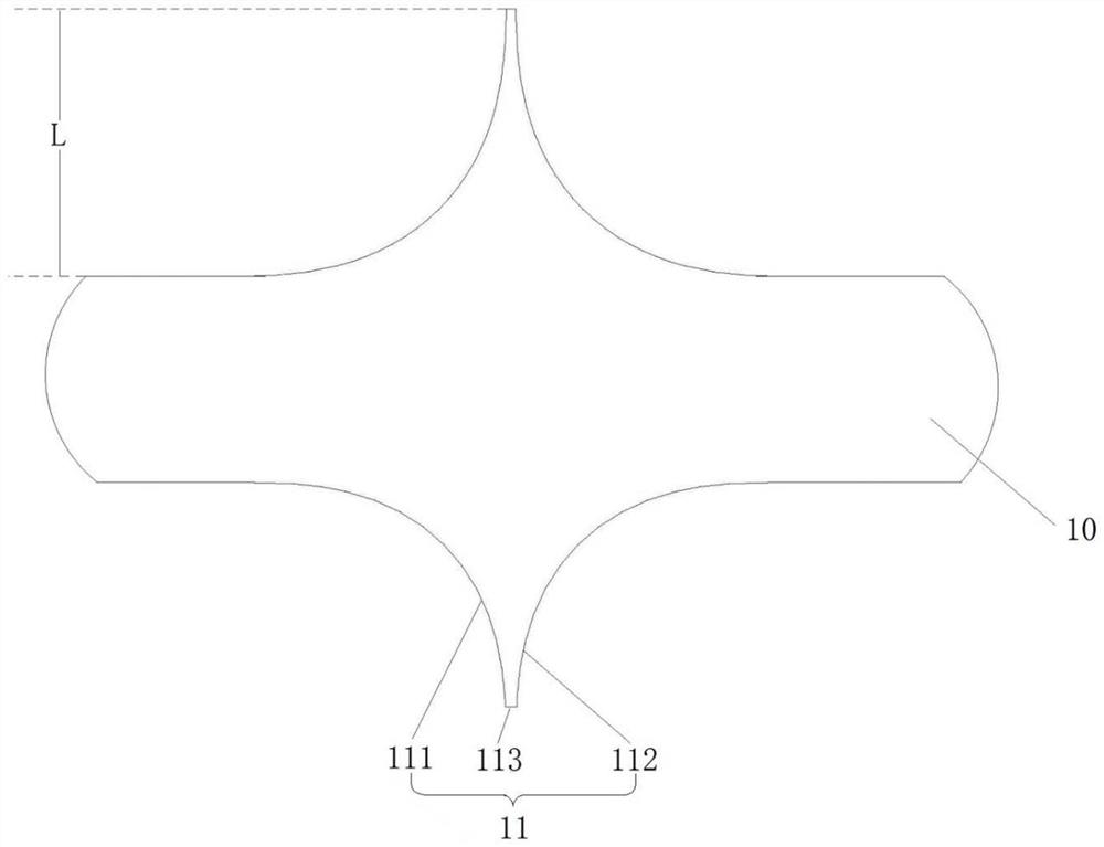
The embodiment of the application provides a transfer printing plate, a preparation method of a to-be-cut panel and a to-be-cut panel. At least two cofferdam structures in a transfer printing plate base plate are respectively enclosed to form at least two transfer printing areas, a plurality of convex part structures are arranged in the cofferdam structures at two opposite side edges of each transfer printing area, and the convex part structures extend towards the transfer printing areas in a direction parallel to the base plate; the convex part structures of one cofferdam structure are in one-to-one correspondence with the convex part structures of the other cofferdam structure; a plurality of corresponding the convex part structures are virtually connected, each transfer printing area isdivided into a plurality of sub-transfer-printing areas, and the sub-transfer-printing areas are used for preparing sub-organic layers, so that the sub-organic layers correspond to sub-display areasof a to-be-cut panel and peripheral areas surrounding the sub-display areas. In this way, the area between the R corners of every two adjacent sub-display areas in the to-be-cut panel is not covered with PI materials, and a technical problem that a GOA unit cannot work normally due to the PI materials is solved in the follow-up process.

Description

technical field [0001] The present application relates to the technical field of display devices, and in particular, to a transfer plate, a method for preparing a panel to be cut, and a panel to be cut. Background technique [0002] In the production process of the thin film transistor liquid crystal display panel, it is necessary to coat the PI (PolyImide, polyimide) alignment layer, and the rotation of the liquid crystal is given a top tilt angle by PI to stabilize the rotation direction of the liquid crystal, thereby making the liquid crystal display panel. Display works normally. At present, the method of coating the PI alignment layer includes dropping the PI material on an APR (Asahikasei Photosensitive Resin, photosensitive resin) plate, and then transferring the PI material to the substrate from the APR plate. [0003] In order to improve the aesthetics of mobile products such as mobile phones and tablet computers, the four top corners of mobile products on the mark...

Claims


Application Information

Patent Timeline
Patent Type & Authority Applications(China)
IPC IPC(8): G02F1/13G02F1/1337
CPCG02F1/1303G02F1/133723
Inventor 赵彦礼李晓吉吴海龙陈刚杨生栗鹏齐智坚
Owner BOE TECH GRP CO LTD
Learn More