Rubber coating and feeding mechanism of winding machine
What is Al technical title?
Al technical title is built by PatSnap Al team. It summarizes the technical point description of the patent document.
A winding machine and encapsulation technology, used in coil manufacturing, electrical components, inductor/transformer/magnet manufacturing, etc., can solve the problems of reducing labor intensity, labor cost, labor intensity, and poor encapsulation effect.
Active Publication Date: 2020-09-25
苏州创易技研股份有限公司
View PDF9 Cites 3 Cited by
Summary
Abstract
Description
Claims
Application Information
AI Technical Summary
This helps you quickly interpret patents by identifying the three key elements:
Problems solved by technology
Method used
Benefits of technology
Problems solved by technology
[0003] The technical problem to be solved by the present invention is to provide a glue-wrapping and glue-feeding mechanism for winding machines. Adhesive tapes, detecting tapes, clamping tapes, positioning tapes on the surface of workpieces to be glued, laminating a variety of different tapes on workpieces, adjusting the attenuation of tapes, and cutting off various tapes after laminating operations And a series of operations, and the above-mentioned operation process does not require manual participation, which can not only greatly reduce the labor intensity of workers and reduce the labor cost of enterprises, but also has the advantages of high encapsulation efficiency, good encapsulation effect and high encapsulation precision. , so that it not only effectively solves the problems of low encapsulation efficiency, low encapsulation precision, poor encapsulation effect, high labor intensity of workers and high labor cost of enterprises in the traditional way of encapsulating products by manual operation. It also solves the problem that the current automatic gluing machine cannot pack a variety of different tapes on the product, which leads to high purchase costs for the enterprise, a large area required for placing the equipment, and the need for manual feeding of the product to connect between the two equipment. The problem
Method used
Image
Click on the blue label to locate the original text in one second.
Reading with bidirectional positioning of images and text.
Examples
Embodiment Construction
[0024] In order to facilitate the understanding of the present invention, the present invention will be described more fully below with reference to the relevant drawings. The preferred embodiments of the present invention are shown in the drawings. However, the present invention can be implemented in many different forms and is not limited to the embodiments described herein. On the contrary, the purpose of providing these embodiments is to make the disclosure of the present invention more thorough and comprehensive.
[0025] Unless otherwise defined, all technical and scientific terms used herein have the same meaning as commonly understood by those skilled in the technical field of the present invention.
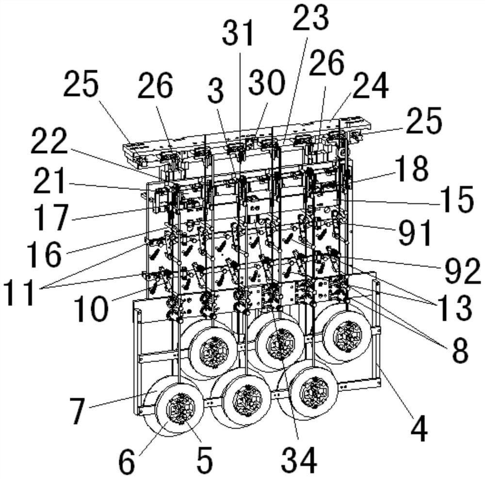
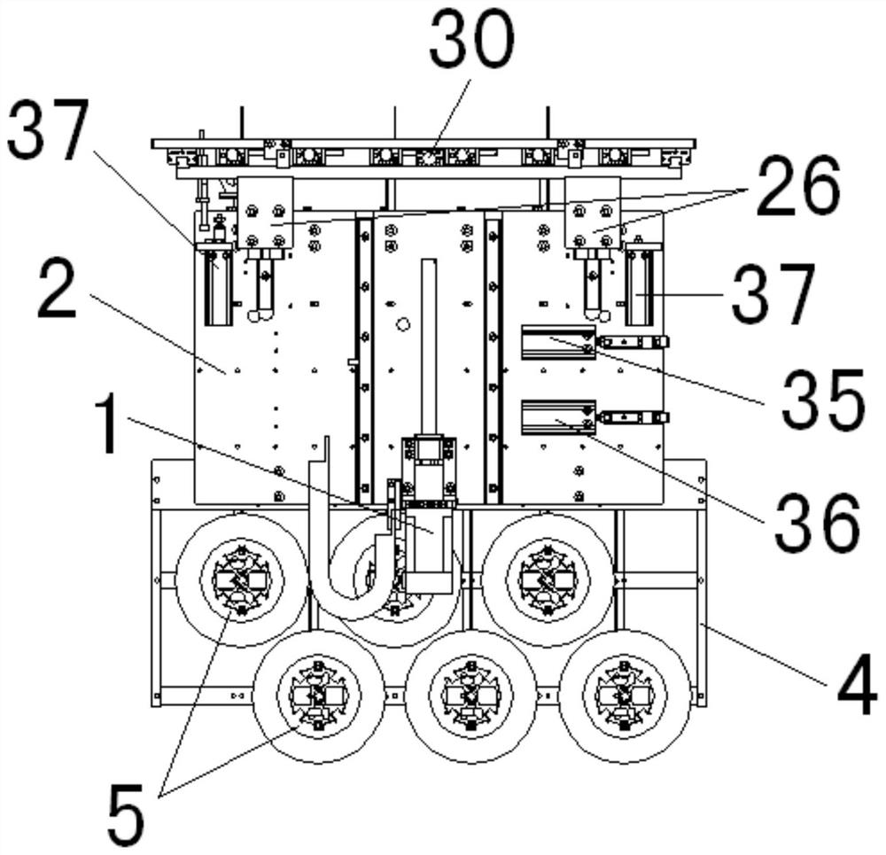
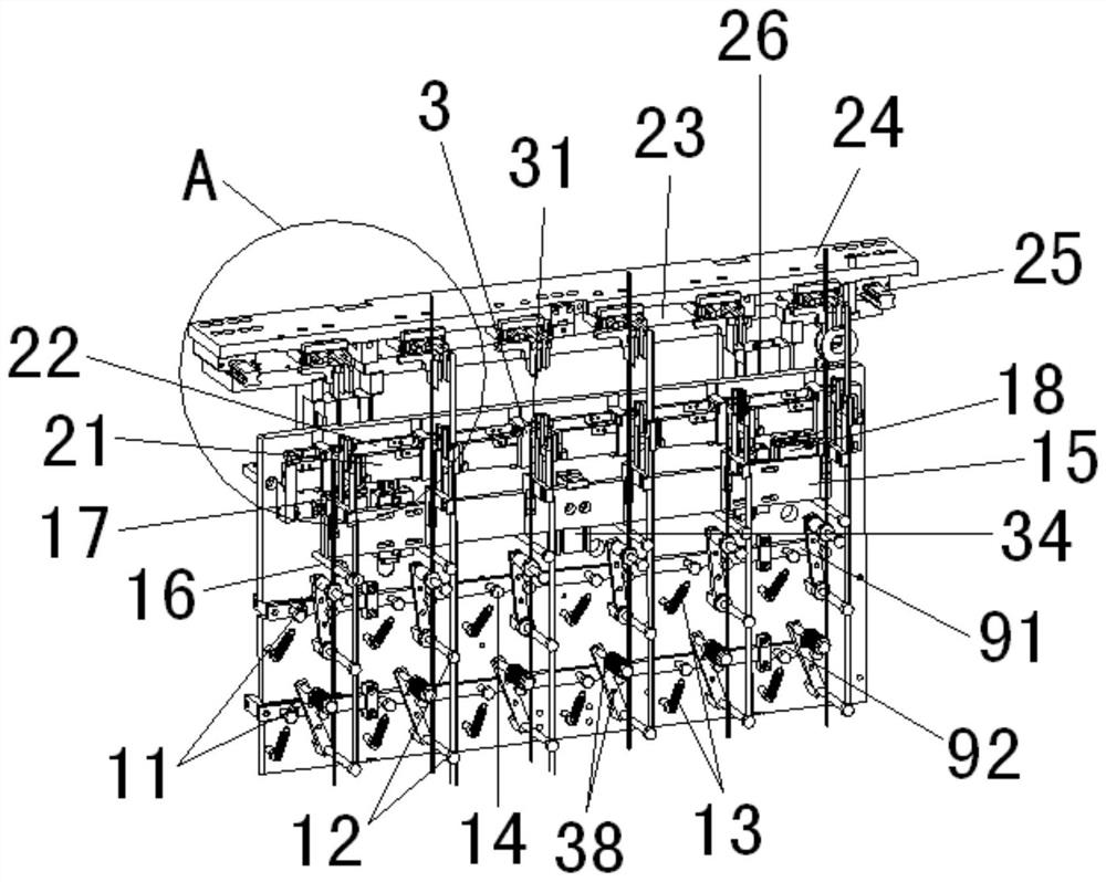
[0026] In this embodiment, refer to Figure 1 to Figure 6 As shown, the glue-packing and glue-feeding mechanism of the winding machine of the present invention includes: the up and down moving motor 1; the base plate 2, which is used to install on one side of the up and down...
PUM
Abstract
The invention relates to a rubber coating and feeding mechanism of a winding machine. The mechanism comprises an up-and-down moving motor, adhesive tape disc rack, an adhesive tape disc and an adhesive tape detection wheel, a first attenuation connecting rod, a second attenuation connecting rod, an attenuation rod, an attenuation shaft, a reset spring, a limiting screw, a tape pulling transverse plate, an adhesive tape shaft, an insulating tape clamping air cylinder, a retaining wall adhesive tape clamping air cylinder, an insulating tape lower clamp, a retaining wall adhesive tape lower clamp, a front adhesive tape clamping plate, a rear adhesive tape clamping plate, a bag pulling lower transverse plate, a bag pulling upper transverse plate and a transverse plate moving guide rail assembly. Due to the overall structural design, various different adhesive tapes can be automatically wrapped on a workpiece on the same equipment, a series of operations such as adhesive tape conveying, adhesive tape detecting, adhesive tape clamping, adhesive tape positioning to the surface of a to-be-coated workpiece, coating of various different adhesive tapes on the workpiece, attenuation adjustmenton the adhesive tapes and cutting off of the various different adhesive tapes after coating operation are also realized. The rubber coating and feeding mechanism has the advantages of being high in rubber coating efficiency, good in rubber coating effect and high in rubber coating precision.
Description
Technical field [0001] The invention relates to a gluing and feeding mechanism for a winding machine. Background technique [0002] The traditional encapsulation of products generally uses human hands to encapsulate the wires. Manual encapsulation not only has the disadvantages of low encapsulation efficiency, low encapsulation precision and poor encapsulation effect, but also leads to high labor intensity and enterprise The labor cost is high. Later, some encapsulation equipment appeared on the market. For example, the encapsulation mechanism with the invention patent number "202010324324.6" and the utility patent number "202020617554.7" applied by the applicant on the same day before, although it can automatically encapsulate, but each The equipment can only be packed with one kind of tape. When the product needs to pack a variety of different tapes, the company needs to purchase multiple equipment to pack a variety of different tapes for the product, which not only leads to h...
Claims
Application Information
Patent Timeline
Application Date:The date an application was filed.
Publication Date:The date a patent or application was officially published.
First Publication Date:The earliest publication date of a patent with the same application number.
Issue Date:Publication date of the patent grant document.
PCT Entry Date:The Entry date of PCT National Phase.
Estimated Expiry Date:The statutory expiry date of a patent right according to the Patent Law, and it is the longest term of protection that the patent right can achieve without the termination of the patent right due to other reasons(Term extension factor has been taken into account ).
Invalid Date:Actual expiry date is based on effective date or publication date of legal transaction data of invalid patent.