Stick-slip piezoelectric actuator for realizing bidirectional driving and control method

A piezoelectric driver, bidirectional driving technology, applied in piezoelectric effect/electrostrictive or magnetostrictive motors, electrical components, generators/motors, etc., can solve problems such as poor load capacity and low driving speed, and achieve Broaden usage scenarios, increase load capacity, increase driving efficiency and the effect of driving force

Active Publication Date: 2020-09-25
WUHAN UNIV
View PDF3 Cites 4 Cited by
  • Summary
  • Abstract
  • Description
  • Claims
  • Application Information

AI Technical Summary

Problems solved by technology

[0005] Most of the current stick-slip piezoelectric actuators can only move in one direction, and there are problems such as poor load capacity and low driving speed.

Method used


Image

  • Stick-slip piezoelectric actuator for realizing bidirectional driving and control method
  • Stick-slip piezoelectric actuator for realizing bidirectional driving and control method
  • Stick-slip piezoelectric actuator for realizing bidirectional driving and control method

Examples


Embodiment 1

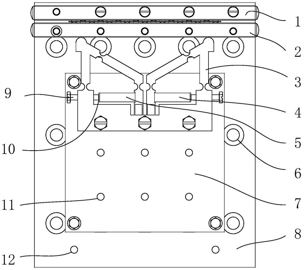
[0052] The base 8 is fixed on the vibration isolation table by screws through the fixing hole group 6 thereon, and the vibration isolation table should be able to reduce or compensate various disturbance factors from the environment.

[0053] The XY micro-motion platform 7 and the guide rail 1 are respectively fixed on the base by screws through the fixing hole groups 12 and 21 on the base.

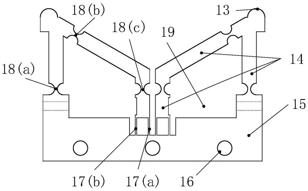
[0054] The positive piezoelectric ceramic 5 and the negative piezoelectric ceramic 4 are respectively fixed at the piezoelectric ceramic installation groove 19 of the compliant drive mechanism 3 by adjusting screws 9, and the piezoelectric ceramics 4 and 5 are respectively in contact with the pseudo-rigid rod 14, and are installed symmetrically. The piezoelectric ceramics 4 and 5 are separated from the adjusting screw by a spacer. Pay attention to alignment when installing piezoelectric ceramics.

[0055] Rotate the adjusting screw 9 until the proper pre-tightening force is reached betwe...

Embodiment 2

[0059] Install and adjust the driver according to the implementation method in Example 1.

[0060] A sawtooth wave with a slow rising phase and a fast falling phase is passed to the piezoelectric ceramic corresponding to the driving direction of the slider, and the other piezoelectric ceramic does not input a signal.

[0061] Wherein, the driving direction includes a positive driving direction and a negative driving direction.

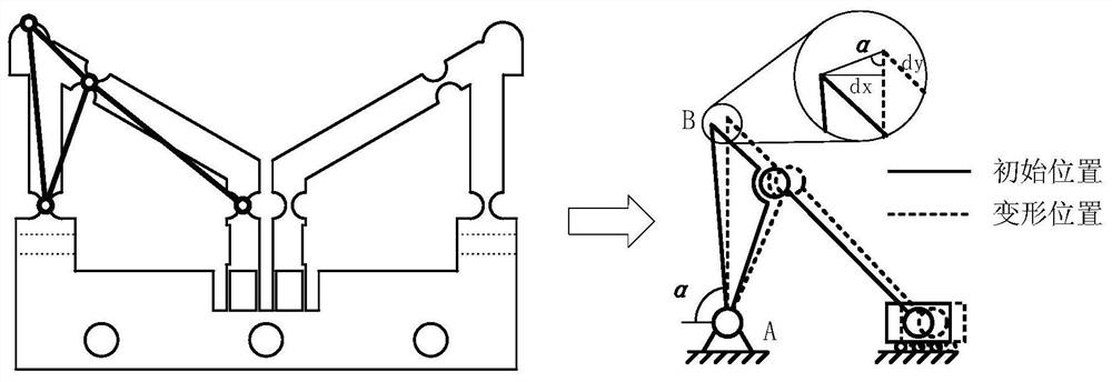
[0062] When the driving signal rises slowly, the piezoelectric ceramic slowly elongates, which drives the compliant driving mechanism 3 to deform, so that the driving foot 13 has a displacement dx in the driving direction and a pressing displacement dy perpendicular to the direction of the guide rail. This positive The pressing displacement makes the positive pressure between the driving foot 13 and the slider 2 increase, and the maximum static friction force increases to ensure that the two are "sticky" together, and the driving foot 13 and the slider...

Embodiment 3

[0067] Install and adjust the driver according to the implementation method in Example 1.

[0068] Determination of the driving signal time: select the forward direction as the driving direction of the piezoelectric driver, drive the piezoelectric ceramic 5 in the forward direction with a sawtooth wave signal, the duty cycle of the sawtooth wave signal is 90%, and the signal time is 1min. After 1 min, the piezoelectric ceramic 5 is positively driven to continue to maintain the energized state to stabilize the slider. Measure the displacement of the slider within 1min, and the speed of the slider under the changed sawtooth wave signal can be calculated.

[0069] Before driving, it is necessary to clarify the driving displacement, and then according to the speed calculated in the previous step and combined with the displacement to be driven, the time to pass the signal can be calculated. A signal corresponding to the length of time is passed to the selected piezoelectric cerami...


PUM


Abstract

The invention relates to a stick-slip piezoelectric actuator capable for realizing bidirectional driving and a control method. The actuator is composed of a base, a compliant driving mechanism, a sliding block, two stacked piezoelectric ceramics and the like. A sawtooth wave voltage signal is amplified by the power amplifier and then applied to the piezoelectric ceramic, and the sliding block canbe driven to move to a specific position at a target speed in the positive direction and the negative direction by adjusting the amplitude and the frequency of the voltage signal. According to the bidirectional stick-slip piezoelectric actuator, the compliant driving mechanism is adopted, so that the structure is simple, precise and rapid movement can be achieved, and the load capacity and the driving speed can be greatly improved through the adopted special structure.

Description

technical field [0001] The invention relates to the technical field of precision driving, in particular to a stick-slip piezoelectric driver capable of bidirectional motion. Background technique [0002] The precision positioning system is a complete system for precise adjustment of the translation and rotation of the target object in multiple degrees of freedom in space. It is widely used in aerospace, precision operating systems, biotechnology, intelligent robots, optical systems, ultra-precision instruments and other fields. The core of the precision positioning system is to use a precision driver to drive the target object to achieve the expected high-precision movement, and its precision reaches the micro / nano level (usually between several nanometers and hundreds of nanometers). At present, many precision drive systems still use manual or electric drive, but with the rapid development of these fields, higher resolution, high precision, large stroke, high-speed response...

Claims


Application Information

Patent Timeline
IPC IPC(8): H02N2/02H02N2/04H02N2/06
CPCH02N2/021H02N2/028H02N2/04H02N2/043H02N2/06H02N2/065
Inventor 凌杰肖晓晖邱灿程冯朝明敏叶婷婷
Owner WUHAN UNIV
Why Eureka
Try Eureka