Al technical title is built by PatSnap Al team. It summarizes the technical point description of the patent document.
A technology for electrical automation and control boxes, which is applied in the direction of electrical components, electrical equipment structural parts, electrical equipment shells/cabinets/drawers, etc., which can solve the inconvenient wire fixing work, inconvenient electrical equipment cooling, and inconvenient wire fixing and separation Work and other problems to achieve the effect of preventing the temperature from being too high
Inactive Publication Date: 2020-09-25
SHANDONG LABOR VOCATIONAL & TECHN COLLEGE
View PDF6 Cites 1 Cited by
Summary
Abstract
Description
Claims
Application Information
AI Technical Summary
This helps you quickly interpret patents by identifying the three key elements:
Problems solved by technology
Method used
Benefits of technology
Problems solved by technology
[0005] In order to solve the above technical problems, the present invention provides an electrical automation control box to solve the problem that the existing electrical automation control box is inconvenient to lift and lower the operation panel when working, and it is inconvenient to fix and separate the wires during use. Work and the inconvenience of fixing the wires connected to the outside and the inconvenient cooling of electrical equipment
Method used
Image
Click on the blue label to locate the original text in one second.
Reading with bidirectional positioning of images and text.
Examples
Embodiment Construction
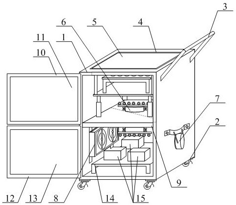
[0035] The present invention is described in detail below in conjunction with accompanying drawing, as appended figure 1 And attached figure 2As shown, an electric automation control box includes a control box 1, a movable brake wheel 2, a push rod 3, a lifting hole 4, a liftable operation panel structure 5, a fixed branch pipe structure 6, and a protective and fixed line pipe. Structure 7, pluggable cooling cooling box structure 8, partition plate 9, first revolving door 10, first observation piece 11, second revolving door 12, second observation piece 13, connecting seat 14 and power equipment assembly 15, The moving brake wheels 2 are respectively bolted to the four corners of the lower end of the control box 1; the push rod 3 is bolted to the upper right side of the control box 1; the lifting hole 4 is opened in the middle of the upper end of the control box 1 Position; the liftable operating panel structure 5 is installed on the upper end of the partition plate 9; the f...
PUM
Abstract
The invention provides an electrical automation control box. The electrical automation control box comprises a control box, a movable brake wheel, a push rod, a lifting hole, a lifting operation platestructure, a fixable wire separation pipe structure, a protectable fixed wire passing pipe structure, a pluggable cooling heat dissipation box structure, a partition plate, a first rotating door, a first observation sheet, a second rotating door, a second observation sheet, a connecting base and a power equipment assembly. A lifting plate, an electric lifting assembly, a supporting base and an operation disc are adopted, the lifting plate can be pushed to move upwards and drive the supporting base and the operation disc to ascend and descend when the electric lifting assembly works in a working process, and the operation disc can ascend and descend conveniently in the working process; a fixing pipe, wire separation rods, wire separation rings, the power equipment assembly and the operation disc are adopted, and therefore, when the power equipment assembly and the operation disc are connected through wires in the working process, the connected wires can be isolated through the wire separation rings, and the situation that the wires are overheated in the working process, and affect work is prevented.
Description
technical field [0001] The invention belongs to the technical field of control boxes, in particular to an electric automation control box. Background technique [0002] The operating end face of the electrical automation control box is generally all located on the box door of the control box, and several operating buttons are arranged on the operating end face. [0003] However, the existing electrical automation control box still has the disadvantages of inconvenient lifting and lowering of the operating panel during work, inconvenient fixing and separating of the wires during use, and inconvenient fixing of the wires connected to the outside and inconvenient installation of electrical appliances. The problem of cooling down the equipment. [0004] Therefore, it is very necessary to invent a kind of control box of electric automation. Contents of the invention [0005] In order to solve the above technical problems, the present invention provides an electrical automatio...
Claims
Application Information
Patent Timeline
Application Date:The date an application was filed.
Publication Date:The date a patent or application was officially published.
First Publication Date:The earliest publication date of a patent with the same application number.
Issue Date:Publication date of the patent grant document.
PCT Entry Date:The Entry date of PCT National Phase.
Estimated Expiry Date:The statutory expiry date of a patent right according to the Patent Law, and it is the longest term of protection that the patent right can achieve without the termination of the patent right due to other reasons(Term extension factor has been taken into account ).
Invalid Date:Actual expiry date is based on effective date or publication date of legal transaction data of invalid patent.