
Automatic harvesting, cutting and smashing machine for promoting straw returning

A pulverizer and crushing mechanism technology, which is applied to the chassis of harvesters, cutters, agricultural machinery, etc., can solve problems such as inconvenience to residents, unfavorable dissolution of straw debris, respiratory diseases, etc.

Inactive Publication Date: 2020-09-29
安徽奉念城机电设计服务有限公司
View PDF14 Cites 0 Cited by
  • Summary
  • Abstract
  • Description
  • Claims
  • Application Information

AI Technical Summary

Problems solved by technology

The disadvantages are: 1. The traditional pulverizer does not have the function of traveling, and can only crush the straw at a fixed point, resulting in the accumulation of the discharged straw debris, which is not conducive to the dissolution of the straw debris by the soil. 2. The straw debris is too small. Due to the wind, the straw debris will be blown into the air, causing inconvenience to the surrounding residents. If inhaled by the human body, it may also cause respiratory diseases. 3. The straw standing in the field cannot be automatically harvested and crushed, and manual labor is required It assists in putting the straw into the crushing box for crushing, which greatly reduces the efficiency of crushing and returning to the field, and increases the labor intensity of farmers

Method used


Image

  • Automatic harvesting, cutting and smashing machine for promoting straw returning
  • Automatic harvesting, cutting and smashing machine for promoting straw returning
  • Automatic harvesting, cutting and smashing machine for promoting straw returning

Examples


Embodiment Construction

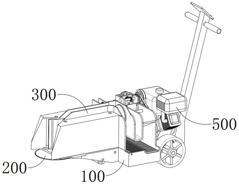
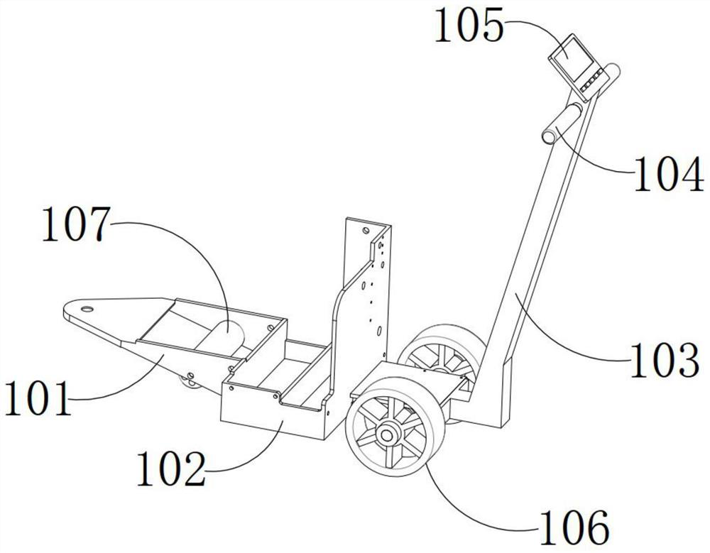
[0079] First of all, it should be noted that the front end mentioned below is the front end along the traveling direction of the traveling bracket 100 , and the rear end mentioned below is the rear end along the traveling direction of the traveling bracket 100 .

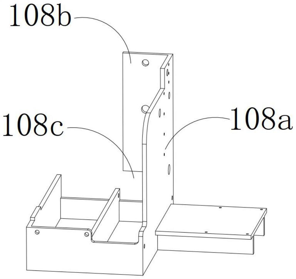
[0080] see Figure 1-27 , an automatic harvesting and cutting shredder for promoting straw returning to the field, which includes a grounded traveling bracket 100, a harvesting mechanism 200 arranged on the traveling bracket 100, a conveying device 300, a crushing mechanism 400 and a power drive device 500, and the harvesting mechanism 200 is set at the front end of the traveling bracket 100 along its own traveling direction and is used for harvesting the straw, and the crushing mechanism 400 is arranged at the rear end side of the traveling bracket 100 along its own traveling direction and is used for cutting and crushing the straw to form 0.5cm For straw debris up to 1 cm in length, the conveying device 300 is arra...


PUM


Abstract

The invention provides an automatic harvesting, cutting and smashing machine for promoting straw returning. The automatic harvesting, cutting and smashing machine comprises a landing advancing bracket, a harvesting mechanism, a conveying device, a smashing mechanism and a power driving device, wherein the harvesting mechanism, the conveying device, the smashing mechanism and the power driving device are arranged on the advancing bracket. The harvesting mechanism is arranged at the front end of the advancing bracket in the advancing direction of the advancing bracket and used for harvesting straws. The smashing mechanism is arranged on one side of the rear end of the advancing bracket in the advancing direction of the advancing bracket and used for cutting and smashing the straws to form straw chippings with the length ranging from 0.5 cm to 1 cm. The conveying device is arranged in the middle of the advancing bracket and located between the harvesting mechanism and the smashing mechanism. The conveying device is used for receiving the straws harvested by the harvesting mechanism and sequentially conducting extrusion bundling, stirring and pushing over, pressing and conveying on thestraws into the smashing mechanism. The power driving device is arranged at the tail of the rear end of the advancing bracket and used for providing driving power for the harvesting mechanism, the conveying device and the smashing mechanism.

Description

technical field [0001] The invention relates to the technical field of straw returning machinery, in particular to an automatic harvesting, cutting and pulverizing machine for promoting straw returning to the field. Background technique [0002] Straw returning to the field is a measure of fertilizing soil fertility and increasing production that is generally valued in the world today. It can increase fertilizer and increase production while eliminating the air pollution caused by straw burning. Straw returning can increase soil organic matter, improve soil structure, loosen soil, increase porosity, reduce capacity, and promote microbial activity and root development of crops. Straw returning to the field has a significant effect on increasing fertilizer and yield, and generally can increase yield by 5% to 10%. However, if the method is not appropriate, it will also lead to an increase in soil pathogens, aggravation of crop diseases, and lack of seedlings (sick seedlings) an...

Claims


Application Information

Patent Timeline
Patent Type & Authority Applications(China)
IPC IPC(8): A01D43/00A01D43/08A01D57/20A01D57/22A01D57/26A01D67/00
CPCA01D43/006A01D43/08A01D57/20A01D57/22A01D57/26A01D67/00
Inventor 不公告发明人
Owner 安徽奉念城机电设计服务有限公司
Learn More