LCD (Liquid Crystal Display) dispensing device

A dispensing device and dispensing technology, which is applied to the surface coating liquid device, coating, etc., can solve the problems of inability to perform automatic rotation processing, manual replacement of tooling, insufficient adaptation to displacement, etc., and achieve continuous and stable dispensing , uniform dispensing time and wide application range

Inactive Publication Date: 2020-09-29
HEFEI PRECISE DISPLAY CO LTD
View PDF9 Cites 2 Cited by
  • Summary
  • Abstract
  • Description
  • Claims
  • Application Information

AI Technical Summary

Problems solved by technology

[0002] Chinese patent (notification number CN206746935U) discloses a multi-head chandelier that can be rotated in layers, although to a certain extent, it solves the problems in the existing technology that cannot be automatically rotated, requires manual replacement of tooling, and low work efficiency. However, there are still obvious deficiencies in the continuous and stable operation of dispensing and adaptation to displacement.

Method used


Image

  • LCD (Liquid Crystal Display) dispensing device
  • LCD (Liquid Crystal Display) dispensing device
  • LCD (Liquid Crystal Display) dispensing device

Examples


Embodiment 1

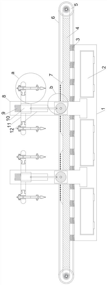
[0020] see Figure 1~3 , in an embodiment of the present invention, an LCD dispensing device includes a horizontally arranged support mounting plate 1, and the front and rear sides of the upper end of the support mounting plate 1 are horizontally provided with transmission Guide material support column 4, a stable driving material guide structure is arranged between the transmission guide material support column 4 on the front and rear sides, the front and rear ends of the middle position of the support installation plate 1 are all left and right symmetrical vertically provided with support installation columns 8, front and rear A synchronous displacement dispensing structure is provided between the support mounting columns 8 on both sides, and the stable driving material guide structure includes an electric drive roller 5 mounted on the left and right sides of the transmission material guide support column 4 through the longitudinal rotation of symmetrically arranged rotating ...

Embodiment 2

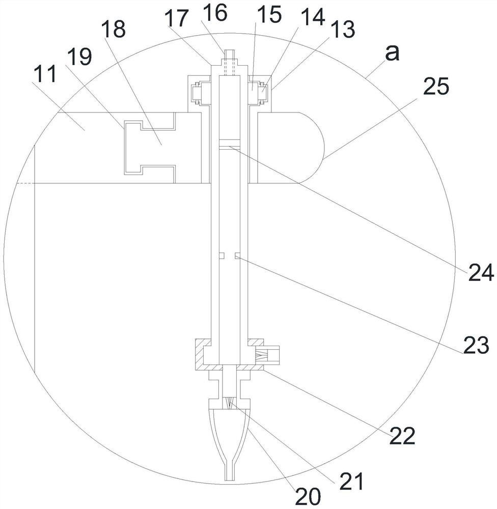
[0022] On the basis of Embodiment 1, the longitudinal guide groove 19 is horizontally provided with a mobile operation plate 25 through the limit guide column 18 outwardly, and the outer side of the guide installation cylinder 17 is provided with a rotating gear ring 15 in cooperation with the limit rotation groove, and the limit The rotation drive gear 14 is provided with the rotation drive gear 14 in the equiangular vertical engagement with the rotation gear ring 15 in the position rotation groove, and the longitudinal guide displacement is realized through the longitudinal guide groove 19 and the moving operation plate 25 in cooperation with the limit guide column 18, and the rotation gear ring 15 and the rotation The meshing transmission of the driving gear 14 realizes the twisting of the guide installation cylinder 17, so that it can be taken out smoothly for the next operation after dispensing, and the air in the guide installation cylinder 17 at the upper end of the lifti...


PUM


Abstract

The invention relates to the field of display screen production, in particular to an LCD dispensing device. The LCD dispensing device comprises a support mounting plate which is arranged horizontally,wherein transmission guide support columns are horizontally arranged on the front and back sides of the upper end of the support mounting plate through spring mounting columns which are arranged vertically at horizontal equal intervals; and a stable driving guide structure is arranged between the transmission guide support columns on the front and back sides. Periodical lifting driving is realized through cooperation of periodical driving motors, so that the device is continuous and stable in dispensing, unified in dispensing time, consistent in dispensing effect, and stable and efficient indispensing operation. Air in a guide mounting barrel at the upper end of a lifting piston is pumped pneumatically like an injector, and a guide mounting barrel at the lower end of the lifting piston is matched with a one-way valve to realize pumping and injection dispensing in order to finish operation. Diverse dispensing positions are realized through rotation displacement and guide movement, sothat the application range is wide. Moreover, the LCD dispensing device is high in injection dispensing speed, free from pause, and high in efficiency.

Description

technical field [0001] The invention relates to the field of display screen production, in particular to an LCD dispensing device. Background technique [0002] Chinese patent (notification number CN206746935U) discloses a multi-head chandelier that can be rotated in layers, although to a certain extent, it solves the problems in the existing technology that cannot be automatically rotated, requires manual replacement of tooling, and low work efficiency. However, there are still obvious deficiencies in the continuous and stable operation of dispensing and adaptation to displacement. [0003] In order to solve the above problems, the present invention is proposed, which realizes the periodical lifting drive through the cooperation of the periodic driving motor, so that the dispensing of the device is continuous and stable, the time of dispensing is uniform, the dispensing effect is consistent, and the dispensing operation has a good stable effect. The air in the diversion in...

Claims


Application Information

Patent Timeline
Patent Type & Authority Applications(China)
IPC IPC(8): B05C5/02
CPCB05C5/0208B05C5/027
Inventor 赵旭
Owner HEFEI PRECISE DISPLAY CO LTD
Why Eureka
Try Eureka