
End cutting device for viscoelastic bar-shaped material

A cutting device and rod-shaped technology, which is applied to the end-cutting device of viscoelastic rod-shaped materials, and in the field of material cutting and processing, can solve problems such as sticking together without separation, uneven incision of bars, and lack of end cutting, etc., to reduce labor Quantity, long-term stable operation, and good processing continuity

Active Publication Date: 2020-09-29
HUBEI UNIV OF TECH
View PDF6 Cites 4 Cited by
  • Summary
  • Abstract
  • Description
  • Claims
  • Application Information

AI Technical Summary

Problems solved by technology

When cutting viscous and elastic rod-shaped materials, due to the particularity of the material, it is often prone to deformation of the rod during the cutting process. There are problems such as sticking to the workbench or cutter, and there is a lack of devices that can separately complete the end cutting of multiple sections of bars with similar length and size requirements. Currently, the above problems can be solved on the market, and these viscous and elastic bars can be processed quickly, efficiently and with high precision. Devices for end-cutting material do not yet exist

Method used


Image

  • End cutting device for viscoelastic bar-shaped material
  • End cutting device for viscoelastic bar-shaped material
  • End cutting device for viscoelastic bar-shaped material

Examples


Embodiment Construction

[0029] Embodiments of the present invention will be further described in detail below in conjunction with the accompanying drawings and examples. The following examples are used to illustrate the present invention, but should not be used to limit the scope of the present invention.

[0030] The preferred embodiments of the present invention will be described in detail below in conjunction with the accompanying drawings, so that the advantages and features of the present invention can be more easily understood by those skilled in the art, so as to define the protection scope of the present invention more clearly.

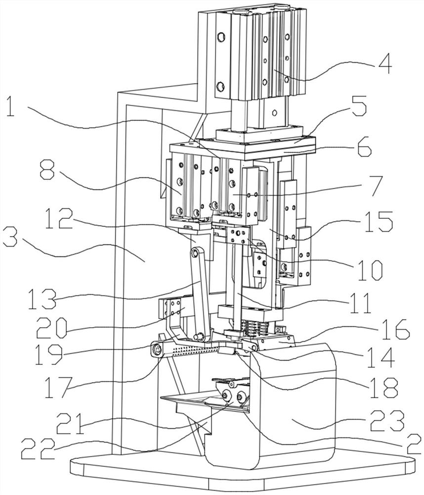
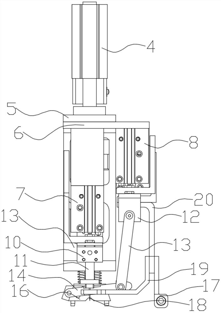
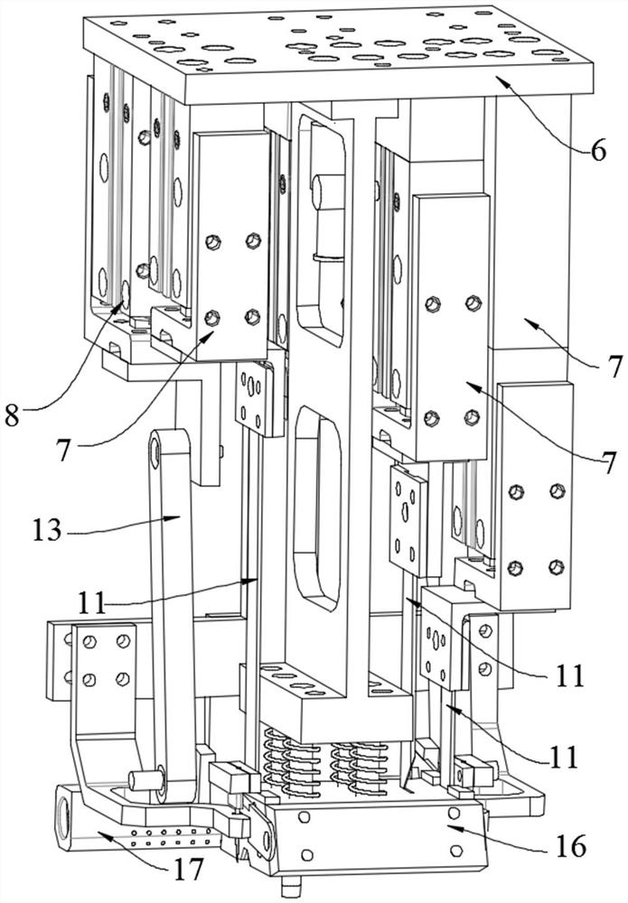
[0031] like Figure 1 to Figure 11 As shown, a kind of end-cutting device of viscoelastic rod-shaped material comprises pressure-cutting device 1, frame 3 and loading platform 21, and described loading platform 21 is installed on the bottom of frame 3, and on described loading platform 21 There is a load tank 24 for placing bars to be cut. The press-cut device 1 is ...


PUM


Abstract

The invention discloses an end cutting device for a viscoelastic bar-shaped material. The end cutting device comprises a pressing and cutting device, a rack and a material carrying platform, wherein the material carrying platform is mounted at the bottom of the rack; a material carrying groove is formed in the material carrying platform; the pressing and cutting device is mounted on the rack abovethe material carrying platform and comprises a pressing plate cylinder, a pressing and cutting moving plate, an upper pressing table, a blowing nozzle bracket, a blowing nozzle cylinder, a discharging rod and a plurality of telescopic cutting devices; the pressing plate cylinder is vertically and fixedly mounted on the rack; the pressing and cutting moving plate is mounted on the pressing plate cylinder; the upper pressing table is mounted at the bottom of the pressing and cutting moving plate through a flexible device; a material taking needle is arranged at each of the two ends of the upperpressing table; the blowing nozzle cylinder is vertically and fixedly mounted on the pressing and cutting moving plate; the blowing nozzle is mounted at a moving telescopic end at the lower part of the blowing nozzle cylinder through the blowing nozzle bracket; and the discharging rod is fixed on the blowing nozzle bracket and moves up and down along with the stretching and retracting of the blowing nozzle cylinder. The end cutting device is high in notch quality and high in precision and can simultaneously finish end cutting of various bar materials with similar length requirements.

Description

technical field [0001] The invention belongs to the field of material processing, and relates to a material cutting and processing technology, in particular to an end cutting device for viscoelastic rod-shaped materials. Background technique [0002] Viscous and elastic rod-shaped materials are referred to as viscoelastic materials, which are widely used in aerospace, chemical, mining, medical and many other industries. When cutting viscous and elastic rod-shaped materials, due to the particularity of the material, it is often prone to deformation of the rod during the cutting process. There are problems such as sticking to the workbench or cutter, and there is a lack of devices that can separately complete the end cutting of multiple sections of bars with similar length and size requirements. Currently, the above problems can be solved on the market, and these viscous and elastic bars can be processed quickly, efficiently and with high precision. Devices for end-cutting ma...

Claims


Application Information

Patent Timeline
IPC IPC(8): B26D1/08B26D1/00B26D5/12B26D7/02B26D7/18B26D7/32B26D7/00
CPCB26D1/00B26D1/08B26D5/12B26D7/00B26D7/02B26D7/1854B26D7/32
Inventor 张铮胡凌辉熊盛辉王孙强王欣姚亚健高博超王蕾
Owner HUBEI UNIV OF TECH
Learn More