Firewood chopping machine for round log
A wood splitting machine and log technology, which is applied to wood splitting devices, wood processing appliances, manufacturing tools, etc., can solve the problems of easy fatigue, labor, and low work efficiency, and achieve the effect of accurate rotation.
- Summary
- Abstract
- Description
- Claims
- Application Information
AI Technical Summary
Problems solved by technology
Method used
Image

Examples
Embodiment 1
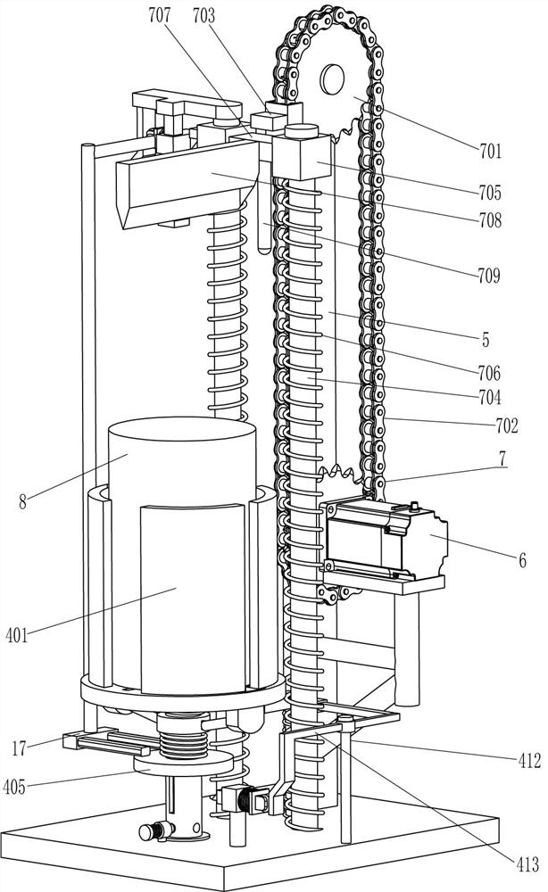
[0023] A log splitter, such as Figure 1-6 As shown, it includes a bottom plate 1, a rotating shaft 2, a support plate 3, a clamping assembly 4, a mounting plate 5, a servo motor 6, and a firewood splitting assembly 7. A support plate 3 is connected, and a clamping assembly 4 is provided between the support plate 3, the rotating shaft 2 and the bottom plate 1. The rear left part of the top of the bottom plate 1 is fixedly connected with a mounting plate 5, and the lower part of the right side of the mounting plate 5 is connected by bolts. Servomotor 6 is installed, between mounting plate 5 and base plate 1 top, be provided with wood splitting assembly 7, splitting wood assembly 7 is fixedly connected with the output shaft of servo motor 6, splitting wood assembly 7 also cooperates with clamping assembly 4.
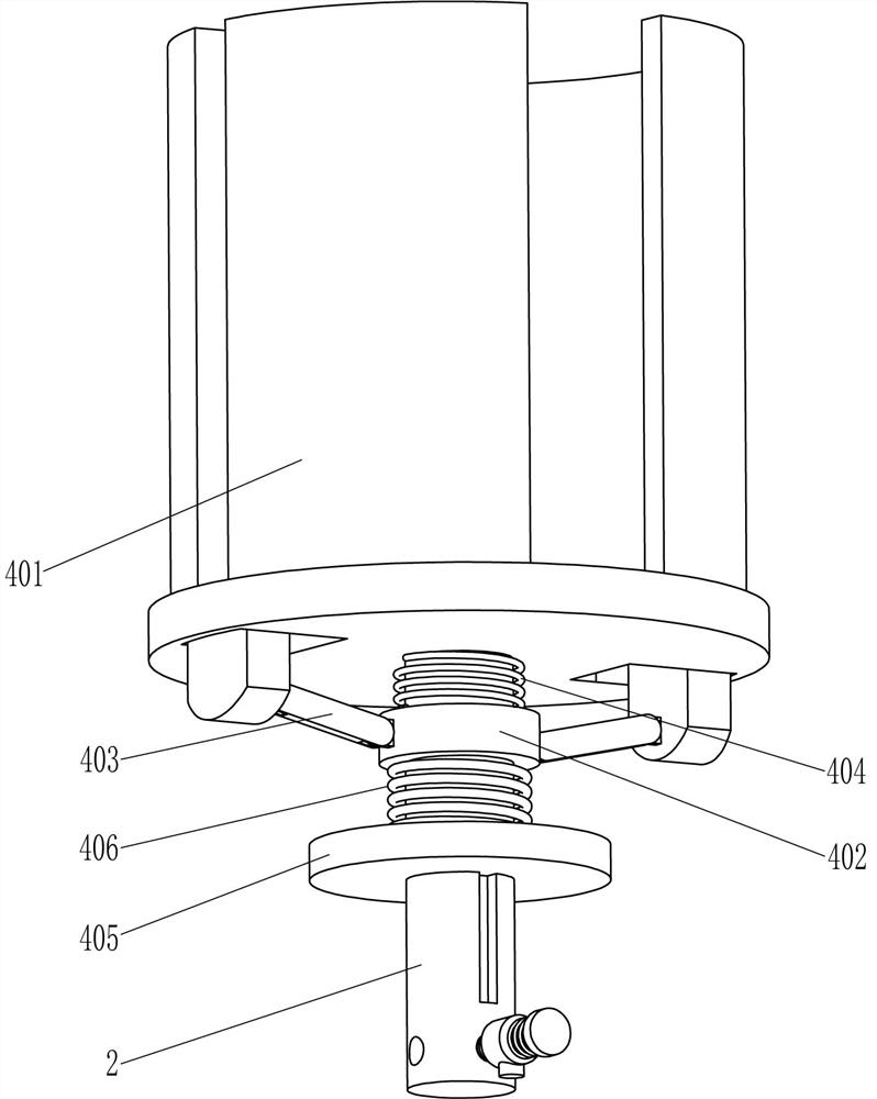
[0024]The clamping assembly 4 includes an arc splint 401, a first sliding sleeve 402, a connecting rod 403, a first spring 404, a first slider 405, a second spring 406, a ...
Embodiment 2
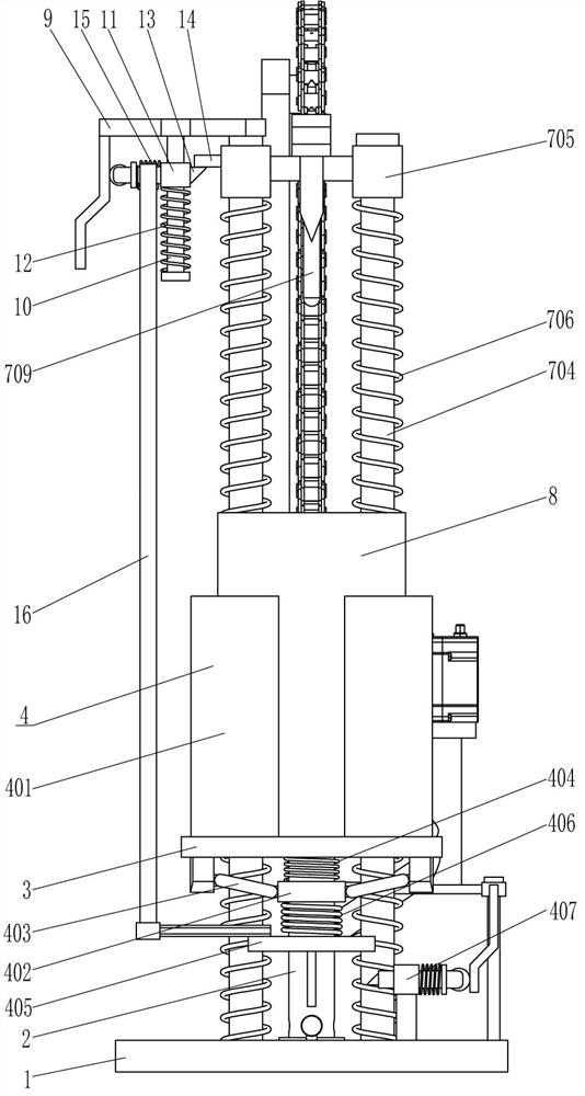
[0030] On the basis of Example 1, such as figure 1 , figure 2 and Figure 6 As shown, it also includes a support frame 9, a second sliding rod 10, a second sliding sleeve 11, a seventh spring 12, a wedge-shaped rod 13, an elastic expansion block 14, an eighth spring 15, a connecting frame 16 and a pressing block 17, left The top of the side guide rod 704 is affixed with a support frame 9, and the middle front part of the top in the support frame 9 is affixed with a second slide bar 10. The second slide bar 10 is slidably provided with a second slide sleeve 11, and the second slide sleeve A seventh spring 12 is wound between the bottom of the 11 and the bottom of the second sliding rod 10, and the rear part of the second sliding sleeve 11 is slidingly provided with a wedge-shaped rod 13, and the left end of the wedge-shaped rod 13 is in contact with the left side of the support frame 9. An eighth spring 15 is wound between the left part of the wedge-shaped rod 13 and the lef...
Embodiment 3
[0033] On the basis of embodiment 1 and embodiment 2, such as Figure 5 As shown, it also includes a fixed sleeve 18, a clamping rod 19 and a ninth spring 20, four grooves 21 are evenly spaced around the lower part of the rotating shaft 2, and a fixed sleeve 18 is fixedly connected to the middle of the front side of the bottom plate 1. The fixed sleeve 18 is located at the front side of the rotating shaft 2, and the fixed sleeve 18 is slidingly provided with a clamping rod 19. The rear end of the clamping rod 19 is located in the front groove 21 to cooperate with it. Ninth spring 20.
[0034] When the log 8 is split into two halves, and the arc splint 401 releases the log 8, the pulling shaft 2 rotates ninety degrees and drives the log 8 to rotate ninety degrees through the support plate 3. When the rotating shaft 2 rotates, the rotating shaft 2 The groove 21 is separated from the lever 19, the rotating shaft 2 drives the lever 19 to move forward, and the ninth spring 20 is s...
PUM
 Abstract
Description
Claims
Application Information
 - R&D Engineer
- R&D Manager
- IP Professional
- Industry Leading Data Capabilities
- Powerful AI technology
- Patent DNA Extraction
Browse by: Latest US Patents, China's latest patents, Technical Efficacy Thesaurus, Application Domain, Technology Topic.
© 2024 PatSnap. All rights reserved.Legal|Privacy policy|Modern Slavery Act Transparency Statement|Sitemap