
Lever-assisted bicycle and lever-assisted multi-wheel vehicle

A technology for assisting bicycles and multi-wheelers, which is applied in vehicle parts, vehicle gearboxes, transportation and packaging, etc., can solve problems such as not very labor-saving, and achieve fast speed

Inactive Publication Date: 2020-09-29
李宝隆
View PDF0 Cites 1 Cited by
  • Summary
  • Abstract
  • Description
  • Claims
  • Application Information

AI Technical Summary

Problems solved by technology

[0002] The current traditional bicycles are all pedals connected to the pedals, the pedals are connected to the large sprocket, the rotation of the large sprocket drives the chain, the chain drives the small flywheel on the rear wheel, and the small flywheel drives the rear wheel to rotate. This transmission method can make Bike to get around, but not very effortlessly

Method used


Image

  • Lever-assisted bicycle and lever-assisted multi-wheel vehicle
  • Lever-assisted bicycle and lever-assisted multi-wheel vehicle
  • Lever-assisted bicycle and lever-assisted multi-wheel vehicle

Examples


Embodiment Construction

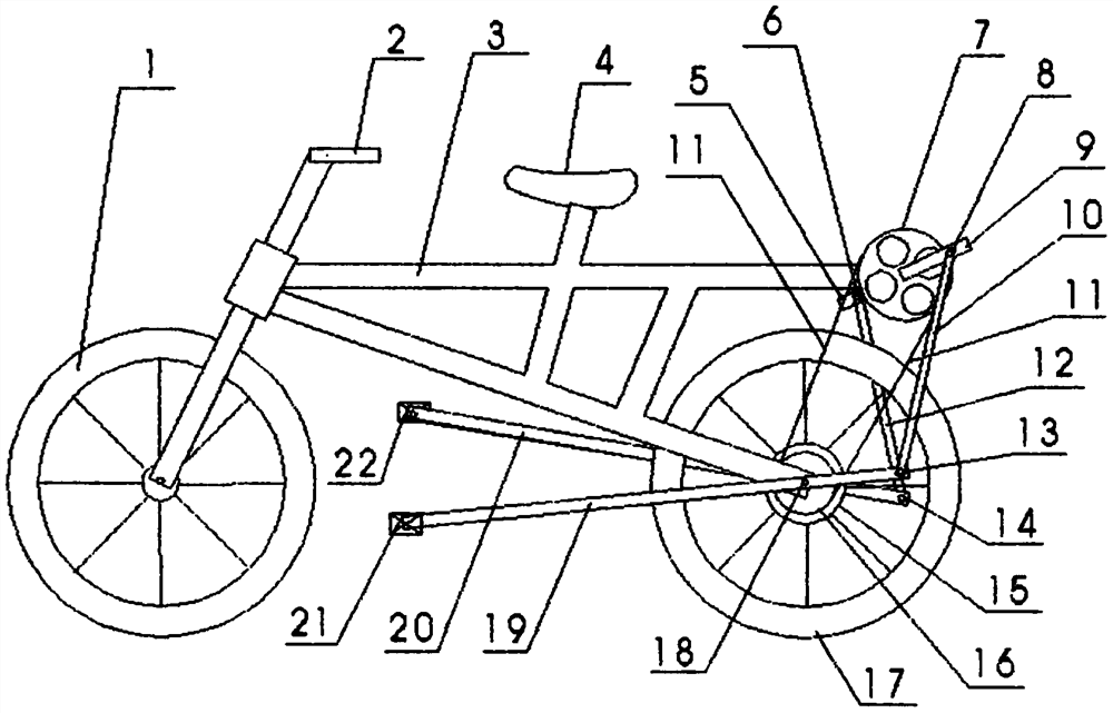
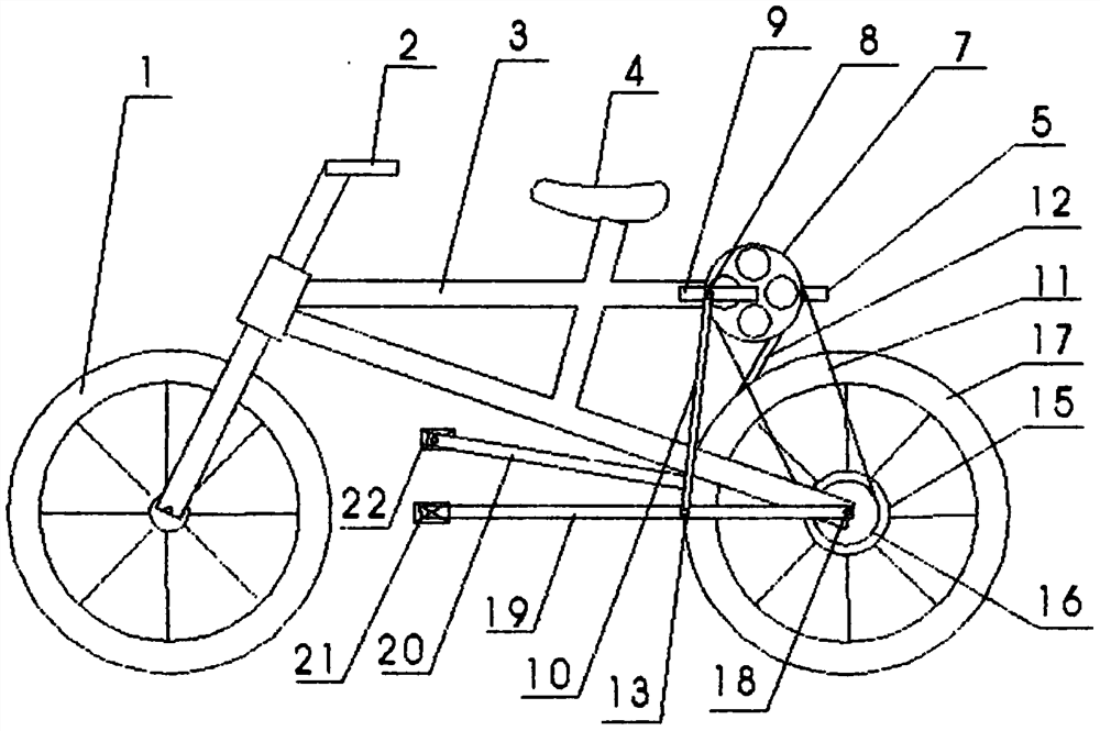
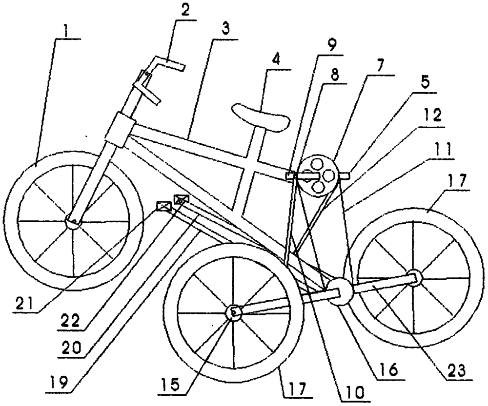
[0017] like figure 1 As shown, the left lever 19 and the right lever 20 are lengthened levers of equal length, the front end of the left lever 19 is connected with the left pedal 21, the front end of the right lever 20 is connected with the right pedal 22, and the left lever fulcrum 18 is connected with the rear wheel central axis (left) Hinged, the right lever fulcrum (not shown) is hinged with the rear wheel central axis (right), the left lever symmetry point 13 is hinged with the low end of the left connecting rod 10, and the high end of the left connecting rod 10 is hinged with the left curved bar 9, and the right Lever symmetry point 14 is hinged with the low one end of right connecting rod 12, and the high end of right connecting rod 12 is hinged with right curved rod 5, and left curved rod 9 right curved rod 5 is connected with large chain wheel 7, and large chain wheel 7 is placed behind Rear wheel 17 tops, large sprocket 7 drives small flywheel 16 and wheel hub 15 and...


PUM


Abstract

The invention provides a lever-assisted bicycle and a lever-assisted multi-wheel vehicle, and relates to a bicycle. The bicycle comprises front and rear wheels, a frame, a saddle, handlebars, left andright pedals, left and right levers, left and right chain rods, a chain, a large chain wheel, a small flywheel and a hub. The left and right levers are movably hinged with the left and right chain rods; the left and right chain rods are movably hinged with left and right curved bars; the left and right curved bars are connected with the large chain wheel; the large chain wheel is arranged above arear wheel, the large chain wheel is rotatably connected with the small flywheel through a chain; the small flywheel is connected with the hub and the rear wheel; the left and right pedals are mounted at front ends of the left and right levers, and fulcrums of the left and right levers are positioned on left and right sides of a rear wheel center shaft; and when the front ends of the levers moveup and down, the chain rod is driven, the chain rod drives the curved bar, the curved bar drives the large chain wheel, the large chain wheel drives the chain, the chain drives the small flywheel, andthe small flywheel drives a hub rear wheel to rotate forwards in cycles. The lever-assisted bicycle is simple in structure, labor-saving, power-assisted and rapid.

Description

technical field [0001] The present application relates to the technical field of pedal bicycles, in particular to a lever-assisted bicycle and a lever-assisted multi-wheeled vehicle. Background technique [0002] The current traditional bicycles are all pedals connected to the pedals, the pedals are connected to the large sprocket, the rotation of the large sprocket drives the chain, the chain drives the small flywheel on the rear wheel, and the small flywheel drives the rear wheel to rotate. This transmission method can make The bike gets around, but not very effortlessly. [0003] The object of the present invention is to provide a lever-assisted bicycle and a lever-assisted multi-wheel vehicle with simple structure, labor saving, power assistance and faster walking speed. Contents of the invention [0004] The technical solution adopted by the present application to achieve the above object is: a lever-assisted bicycle and a lever-assisted multi-wheeled vehicle, compri...

Claims


Application Information

Patent Timeline
IPC IPC(8): B62M1/24B62M9/02
CPCB62M1/24B62M9/02
Inventor 李宝隆
Owner 李宝隆
Learn More