Automatic circulating and reciprocating type material pushing device

A technology of reciprocating and pusher devices, which is applied in transmission devices, transportation and packaging, conveyors, etc., can solve the problems of affecting work efficiency, high maintenance costs, and high cost, and achieves simple control methods, low maintenance costs, and low cost. low cost effect

Inactive Publication Date: 2020-09-29
BENGBU COLLEGE
View PDF7 Cites 8 Cited by
  • Summary
  • Abstract
  • Description
  • Claims
  • Application Information

AI Technical Summary

Problems solved by technology

[0002] At present, material pushing devices are used in many places. The front feeding is generally a non-stop movement. If it is stopped, the efficiency will be greatly reduced. If the double servo cycle is used, the cost is too high, and various cylinders are equipped, and the cost is high. Maintenance The cost is also very high. For some cheap production lines, the electrical control is not very advanced, so electrical controls such as drives and servos cannot be used. Therefore, a simple mechanical method that can automatically reciprocate and push materials is very suitable and necessary. of
[0003] Moreover, for the pusher device in the prior art, once the power-providing mechanism and the link mechanism are loosened or damaged and dropped, the entire pusher device will lose its functionality, and it will no longer be possible to carry the push block to achieve reciprocating motion. At this time, it needs to be disassembled and repaired. This process is very complicated and will cause the pushing device to stop working during the working process, which seriously affects the work efficiency. There is no one that can continue to assist the whole pushing device after the connecting rod mechanism is damaged. Auxiliary bodies that continue to work

Method used


Image

  • Automatic circulating and reciprocating type material pushing device
  • Automatic circulating and reciprocating type material pushing device
  • Automatic circulating and reciprocating type material pushing device

Examples


Embodiment Construction

[0025] The following will clearly and completely describe the technical solutions in the embodiments of the present invention with reference to the accompanying drawings in the embodiments of the present invention. Obviously, the described embodiments are only some, not all, embodiments of the present invention. Based on the embodiments of the present invention, all other embodiments obtained by persons of ordinary skill in the art without making creative efforts belong to the protection scope of the present invention.

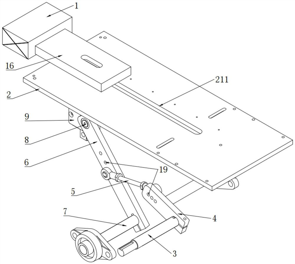
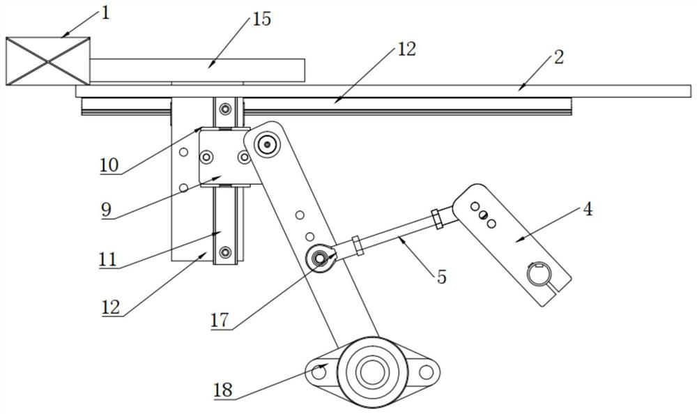
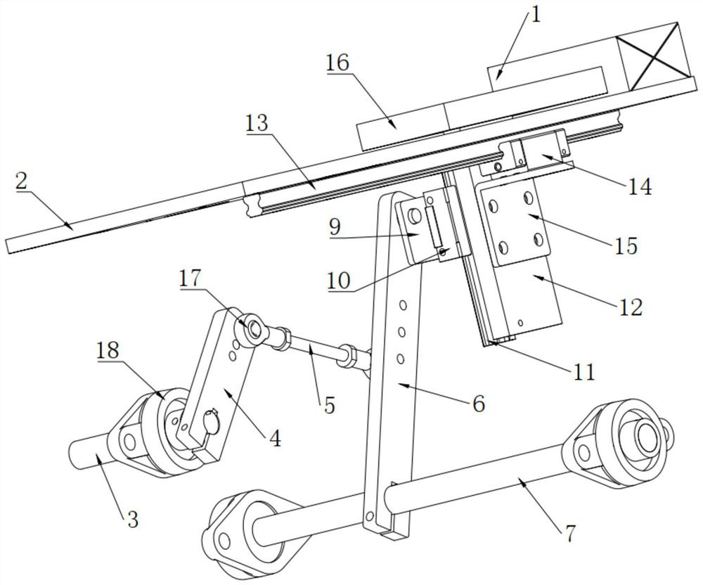
[0026] see Figure 1-8 , the present invention provides a technical solution:

[0027] An automatic cyclic reciprocating pushing device, including a platform 2 for placing a product 1. After the product 1 on the platform 2 is placed, it is pushed by a subsequent slider pushing mechanism, so as to realize the purpose of pushing the material. The platform 2 There is a moving slot 211 through the middle, and the moving slot 211 is opened as a bar-shaped structur...


PUM


Abstract

The invention discloses an automatic circulating and reciprocating type material pushing device. The device comprises a platform used for containing products, a moving groove is formed in the platformin a penetrating mode, and a rotating shaft mechanism, a swing rod mechanism and a sliding block pushing block mechanism are arranged on the platform; and the second rotating shafts are used for being fixedly connected to the second swing rod; the swing rod mechanism comprises a first swing rod, a connecting rod and a second swing rod, and the end, away from the second rotating shaft, of the second swing rod is rotationally connected to an up-down sliding block connecting plate through a rotating bearing. The material pushing device can drive the swing rod and the connecting rod to circularlyrotate only by connecting a chain wheel or a synchronizing wheel from a driving position to provide rotating acting force for the first rotating shaft without a motor, the pushing block can be betterdriven to do non-stop reciprocating motion, the control mode is simple, the manufacturing cost is low, the structure is simple, the operation is convenient, and maintenance cost is lower.

Description

technical field [0001] The invention relates to the technical fields of product conveying, equipment feeding and product steering, in particular to an automatic cycle reciprocating pusher. Background technique [0002] At present, the material pushing device is used in many places. The front feeding is generally a non-stop movement. If it is stopped, the efficiency will be greatly reduced. If the double servo cycle is used, the cost is too high, and there are various cylinders, the cost is high, and the maintenance The cost is also high. For some cheap production lines, the electrical control is not very advanced, so electrical controls such as drives and servos cannot be used. Therefore, a simple mechanical method that can realize automatic cyclic reciprocating push is very suitable and necessary of. [0003] Moreover, for the pusher device in the prior art, once the power-providing mechanism and the linkage mechanism are loosened or damaged and dropped, the entire pusher ...

Claims


Application Information

Patent Timeline
Patent Type & Authority Applications(China)
IPC IPC(8): B65G25/08B65G47/82F16H37/12
CPCB65G25/08B65G47/82B65G2812/12F16H37/124
Inventor 范恒亮魏天路李大胜
Owner BENGBU COLLEGE
Why Eureka
Try Eureka