A high-speed railway rail surface local subsidence lifting system and construction method
A local settlement, high-speed railway technology, applied in the directions of roads, tracks, laying tracks, etc., can solve the problems of mortar accumulation, insufficient density, and limited mortar accumulation, and achieve the effect of improving work efficiency, facilitating movement, and avoiding accumulation.
- Summary
- Abstract
- Description
- Claims
- Application Information
AI Technical Summary
Problems solved by technology
Method used
Image
Examples
specific Embodiment approach 1
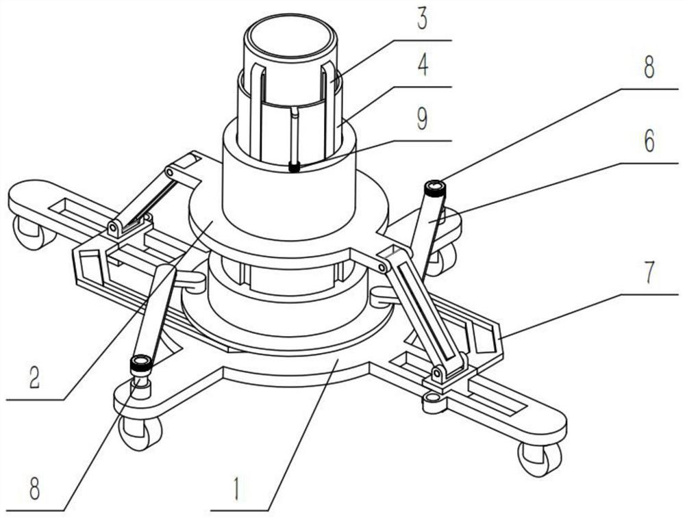
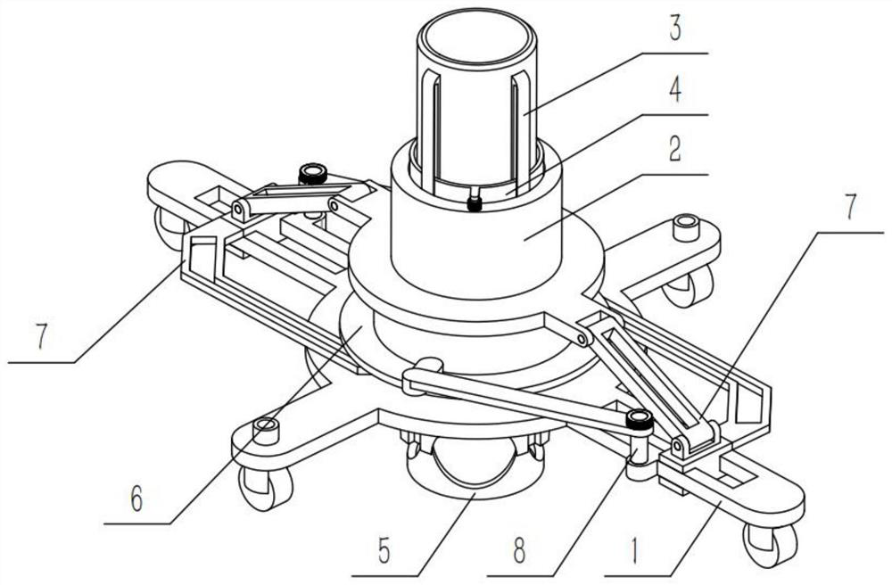
[0037] Combine below Figure 1-11 Describe this embodiment, a high-speed railway rail surface local subsidence lifting system, a high-speed railway rail surface local subsidence lifting system, including a sliding base 1 and an adjusting sliding tube mechanism 2, the lower part of the adjusting sliding tube mechanism 2 is slidably connected to the In the middle part of the sliding base 1, the high-speed railway rail surface local subsidence lifting system also includes an upper connecting pipe 3, an upper adjusting pipe 4, a discharge pipe 5, an adjusting transmission mechanism 6, a connecting mechanism 7, a positioning pin 8 and a positioning ring 9 , the upper end of the upper connecting pipe 3 is fixedly connected in the upper part of the adjusting slide pipe mechanism 2, the upper adjusting pipe 4 is slidably connected to the periphery of the upper connecting pipe 3, and the mortar feeding pipe is connected with the upper The pipes 3 are connected, the lower end of the upp...
specific Embodiment approach 2
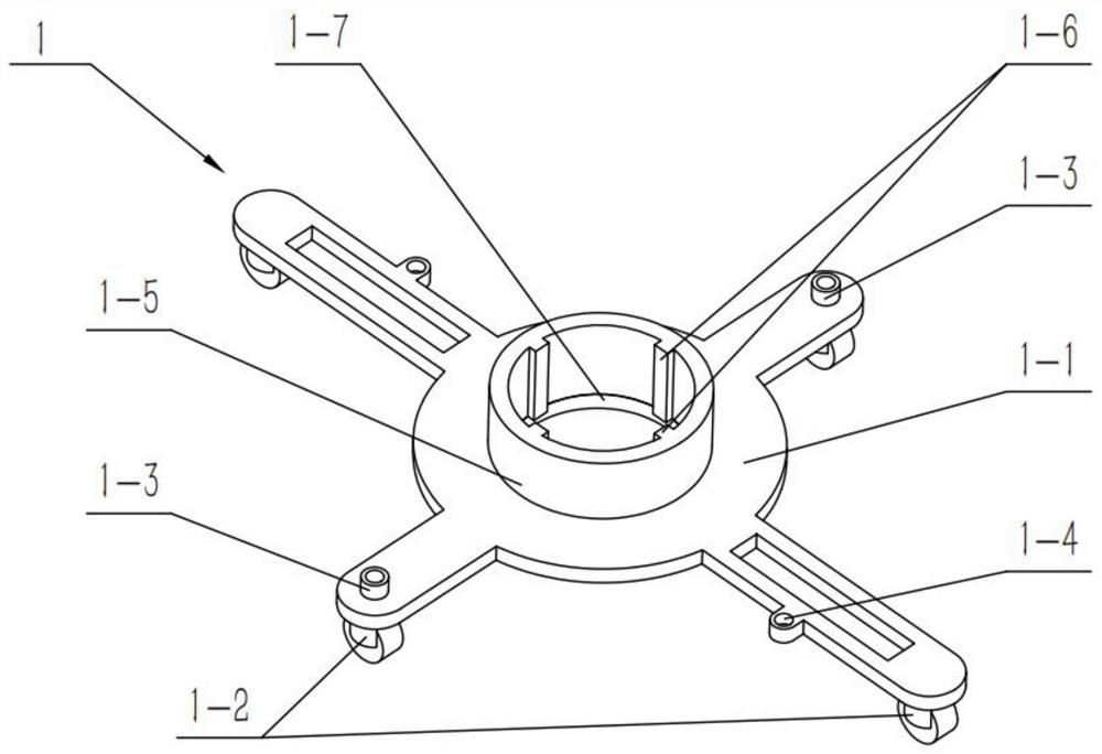
[0038] Combine below Figure 1-11 Describe this embodiment, this embodiment will further explain the first embodiment, the sliding base 1 includes a base 1-1, a universal wheel 1-2, a positioning tube 1-3, a positioning hole 1-4, and a base pipe 1-5 and positioning protrusions 1-6, the four corners of the base 1-1 are provided with universal wheels 1-2, the positioning tube 1-3 is provided with two, and the two positioning tubes 1-3 are symmetrically arranged on the The two sides of the base 1-1, the other two sides of the base 1-1 are centered and symmetrically provided with two positioning holes 1-4, the base pipe 1-5 is arranged in the middle of the base 1-1, its Four positioning protrusions 1-6 are uniformly arranged on the inner wall circumferentially, the lower part of the adjustment sliding pipe mechanism 2 is slidably connected in the base pipe 1-5, and the adjustment transmission mechanism 6 is rotatably connected in the base pipe 1 -5 on.
specific Embodiment approach 3
[0039] Combine below Figure 1-11 This embodiment will be described, and this embodiment will further describe the second embodiment. The lower end of the base pipe 1-5 is provided with an auxiliary ring 1-7.
PUM
 Abstract
Description
Claims
Application Information
 - R&D
- Intellectual Property
- Life Sciences
- Materials
- Tech Scout
- Unparalleled Data Quality
- Higher Quality Content
- 60% Fewer Hallucinations
Browse by: Latest US Patents, China's latest patents, Technical Efficacy Thesaurus, Application Domain, Technology Topic, Popular Technical Reports.
© 2025 PatSnap. All rights reserved.Legal|Privacy policy|Modern Slavery Act Transparency Statement|Sitemap|About US| Contact US: help@patsnap.com


