Working method of concrete pouring device with uniform smoothing effect

A working method and technology of watering device, applied in the directions of roads, road repair, roads, etc., can solve problems such as unfavorable watering work, inability to meet, reduce watering efficiency, etc., and achieve improved practicability and flexibility, smooth and smooth sliding, The effect of reducing watering costs

Inactive Publication Date: 2020-09-29
赵燕虎
View PDF2 Cites 8 Cited by
  • Summary
  • Abstract
  • Description
  • Claims
  • Application Information

AI Technical Summary

Problems solved by technology

[0006] 1. When the designed supporting rod and socket frame drive several sprues to slide horizontally, because only the rotating shaft is used as the connection between the two, the operation of several sprues is not stable, and at the same time only one The supporting rod drives the entire watering mechanism to slide, the friction force is large, and the sliding speed is too slow, which reduces the watering efficiency and is not conducive to the smooth progress of the watering work
[0007] 2. The designed pouring base cannot adjust the flow inside it, so it cannot meet the construction surface of different thickness pouring requirements, so the practicability of the above-mentioned device needs to be improved
[0008] 3. No smoothing mechanism is designed. After the concrete is poured to the surface of the building, it needs to be paved and smoothed manually. Not only is it easy to cause uneven pouring, but it is also time-consuming and labor-intensive. waste

Method used


Image

  • Working method of concrete pouring device with uniform smoothing effect
  • Working method of concrete pouring device with uniform smoothing effect
  • Working method of concrete pouring device with uniform smoothing effect

Examples


Embodiment Construction

[0040]The technical solutions of the present invention will be further described below in conjunction with the accompanying drawings and through specific implementation methods.

[0041] Wherein, the accompanying drawings are only for illustrative purposes, showing only schematic diagrams, rather than physical drawings, and should not be construed as limitations on this patent; in order to better illustrate the embodiments of the present invention, some parts of the accompanying drawings will be omitted, Enlarged or reduced, does not represent actual product size.

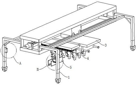
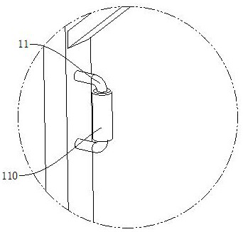
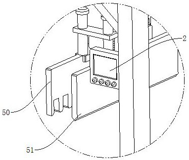
[0042] refer to Figure 1 to Figure 10 The shown concrete pouring device with a uniform smoothing effect includes a carrier frame 1, and also includes a controller 2, a sliding mechanism 3, a laying mechanism 4 and a smoothing mechanism 5, and the controller 2 is fixed on the carrier frame 1 The sliding mechanism 3 is arranged on the top of the bearing frame 1 to support the sliding of the laying mechanism 4 and t...


PUM


Abstract

The invention relates to the field of irrigation devices, and in particular relates to a working method of a concrete pouring device with uniform smoothing effect. The device comprises a bearing frame, a controller, a sliding mechanism, a laying mechanism and a smoothing mechanism; the sliding mechanism comprises a first sliding plate and a transverse sliding assembly; the laying mechanism is arranged at the bottom of the first sliding plate and used for laying cement; the laying mechanism comprises a rotating shaft, a first longitudinal sliding assembly and a plurality of laying pipes; the smoothing mechanism is arranged at the bottom of the second sliding plate and used for smoothing the laid concrete; the smoothing mechanism comprises a rake plate, a scraper blade, a lifting air cylinder and a second longitudinal sliding assembly; the lifting air cylinder, the transverse sliding assembly, the first longitudinal sliding assembly and the second longitudinal sliding assembly are all electrically connected with the controller. According to the concrete pouring device with the uniform smoothing effect and the working method, the pouring amount can be adjusted according to the building surface, meanwhile, concrete accumulation is prevented from being fully utilized, and resource waste is avoided.

Description

technical field [0001] The invention relates to the field of pouring devices, in particular to a working method of a concrete pouring device with a uniform smoothing effect. Background technique [0002] With the rapid development of people's living standards, concrete pouring devices are used more and more frequently in the construction field. The main function of concrete pouring devices is to pour concrete on the construction ground, so that the staff can spread and shape the concrete on the construction ground. . [0003] my country's patent application number: CN201910753708.7; publication date: 2019.11.19 discloses an automatic concrete pouring device for building construction, including a loading frame and a pouring tray. A pouring tray is provided under the middle of the loading frame. A motor 1 is arranged on the top, and a rotating shaft 1 is rotatably connected to the bottom of the motor 1. The beneficial effects of the present invention are: several pouring seat...

Claims


Application Information

Patent Timeline
Patent Type & Authority Applications(China)
IPC IPC(8): E01C19/18E01C19/12
CPCE01C19/12E01C19/185
Inventor 赵燕虎陈颖颖
Owner 赵燕虎
Why Eureka
Try Eureka