Peeling machine

A technology of rotary cutting machine and rotating cylinder, which is applied in the direction of turning equipment, metal processing equipment, turning equipment, etc., which can solve the problems of labor and time, deformation, and wear of the push bearing surface, so as to achieve smooth and stable sliding and durable lifting Sexuality, the effect of safe work

Active Publication Date: 2016-11-09
DAISHO SEIKI CORP
View PDF6 Cites 0 Cited by
  • Summary
  • Abstract
  • Description
  • Claims
  • Application Information

AI Technical Summary

Problems solved by technology

[0006] However, a large rotary cutting machine that cuts workpieces with a diameter exceeding 100 mm has a large and heavy tool holder, so a coil spring with strong elasticity is used, and there is a problem in the manufacturing process and preparation work before the cutting operation: it is difficult to confirm the tool holder. Whether it can slide smoothly or not, and it takes time and effort to manufacture due to the complexity of the structure
[0007] In addition, the tool holder is pushed while the pressing member is in sliding contact with the tool holder with a strong force against the elastic force of the coil spring, so there is a problem that the pressing surface of the pressing member and the pressing receiving surface of the tool holder are easily generated. wear problem
[0008] Furthermore, when the tool holder is moved radially outward in order to cut a workpiece with a larger diameter than the previous cutting operation, if the sliding resistance of the tool holder increases due to fine chips, the tool holder cannot move in the spiral direction. The elastic force of the spring moves outward in the radial direction, and if a workpiece with a larger diameter than the previous cutting operation is fed while the tool holder cannot be avoided, the end of the workpiece may come into contact with the tool holder. problems such as deformation and damage

Method used


Image

  • Peeling machine
  • Peeling machine
  • Peeling machine

Examples


Embodiment Construction

[0021] Hereinafter, the present invention will be described in detail based on the illustrated embodiment.

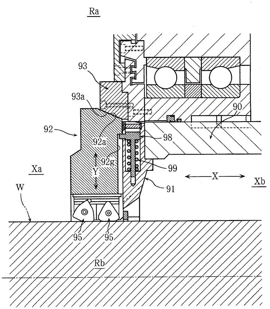
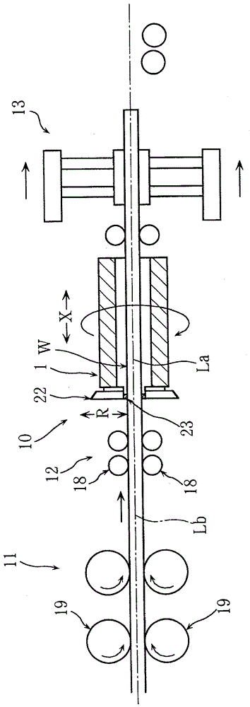
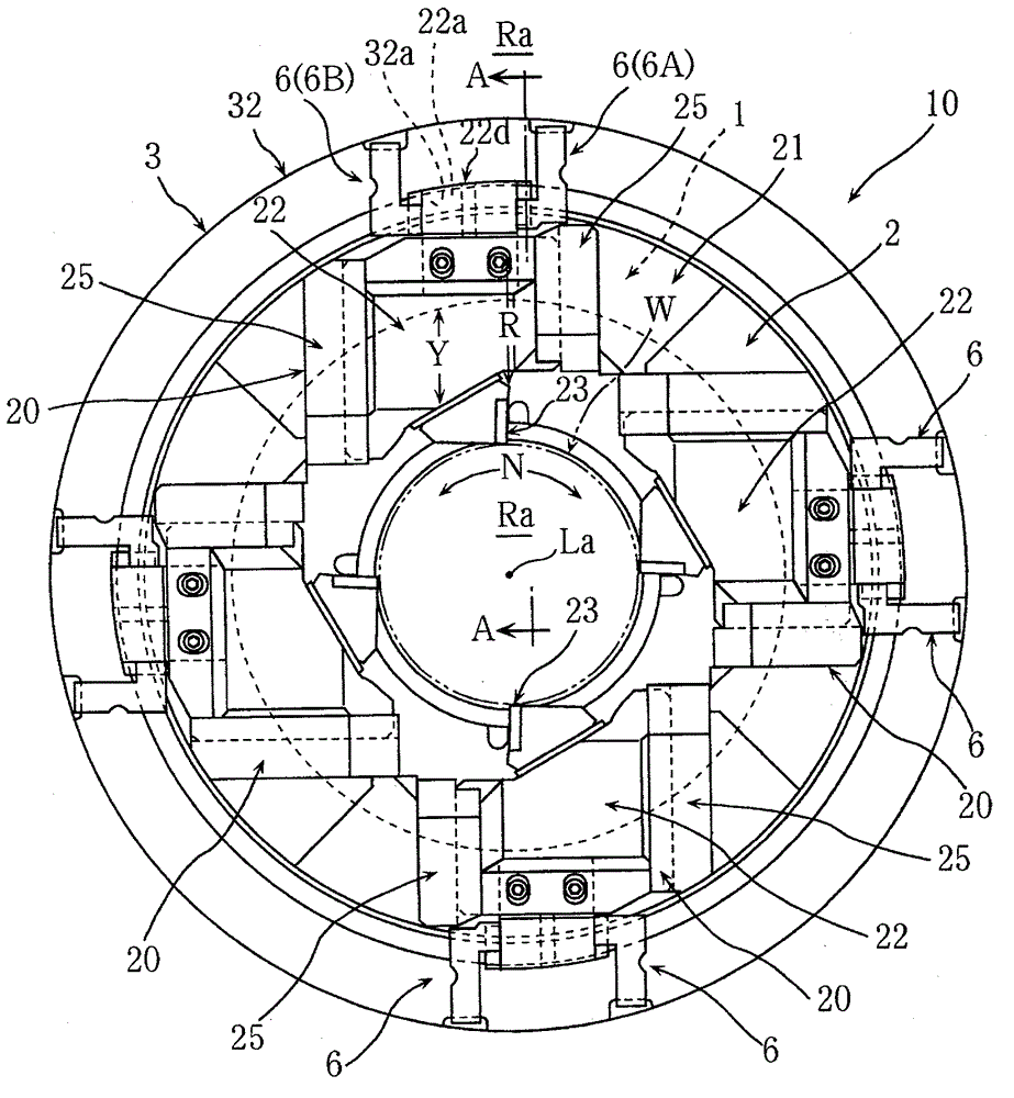
[0022] Such as figure 1 As shown, the rotary cutting machine related to the present invention includes a cutting device 10, a feeding device 11, a guide device 12, and a stage device 13. The cutting device 10 includes a rotating drum 1 and a tool holder 22. The rotating drum 1 is metal The round rod-shaped workpiece W is inserted through and rotates around the rotation axis La under the action of the motor. The aforementioned tool holder 22 is mounted on the rotating drum 1, and rotates around the rotation axis La, and is mounted on the outer peripheral surface of the cutting workpiece W. Blade 23, the aforementioned feeding device 11 is equipped with two sets of feeding rollers 19, 19, the aforementioned feeding rollers 19, 19 are a pair of upper and lower feeding rollers that feed the workpiece W into the rotating drum 1, and the aforementioned guiding device 12 has mult...


PUM


Abstract

To provide a peeling machine being able to easily and swiftly conduct production process and preparation work, excellent in durability, and able to certainly prevent movement of a tool holder to a radial inner side by self weight, a peeling machine is provided with a rotation cylinder (1) to which a work (W) of round rod is inserted, a tool holder (22) attached to the rotation cylinder (1) as to freely slide along a radial direction (R) of the rotation cylinder (1), and a pressing member (3) attached to the rotation cylinder (1) as to freely slide along an axial direction of the rotation cylinder (1); and constructed as that a pressing face (32a) of the pressing member 3 and a pressure-receiving face (22a) of the tool holder (22) are made sliding with inclination on a longitudinal face parallel to a sliding direction (Y) of the tool holder (22), and the tool holder (22) is made sliding to a radial inner side on the longitudinal face by sliding the pressing member (3) to an axial outer side (Ra); and, a hook member (6), hitching the tool holder (22) as to prevent sliding of the tool holder (22) to the radial inner side by self weight, is attached to the pressing member (3).

Description

Technical field [0001] The invention relates to a rotary cutting machine. Background technique [0002] There is a conventional rotary cutting machine as follows: It is provided with a rotating drum and a tool holder, the rotating drum is penetrated by a round rod-shaped workpiece, and the tool holder is attached to the rotating drum and slidably along the radial direction of the rotating drum (for example, Refer to Patent Document 1). [0003] Such as Figure 7 As shown, such a conventional rotary cutting mechanism is provided with a pressing member 93 that is attached to the rotating drum 90 and slidably along the axial direction X of the rotating drum 90, and the pressing surface 93a of the pressing member 93 and the tool holder 92 The pressing receiving surface 92a of the tool holder 92 is in oblique sliding contact in a longitudinal section parallel to the sliding direction Y of the tool holder 92, and the pressing member 93 slides to the axially outer side Xa, whereby the too...

Claims


Application Information

Patent Timeline
IPC IPC(8): B23B5/12
CPCB23B5/12
Inventor 田崎英俊
Owner DAISHO SEIKI CORP
Why Eureka
Try Eureka