
Lower lifting point lifting device and lower lifting point integrated integral lifting method

A technology of hanging point and hydraulic lifter, which is applied in transportation and packaging, load hanging components, construction, etc. It can solve the problems of difficult deformation control, difficult installation and high construction cost, and reduce high-altitude dismantling work , Simplify the form of lifting points and reduce the difficulty of construction

Pending Publication Date: 2020-09-29
天津建工科技有限公司
View PDF0 Cites 3 Cited by
  • Summary
  • Abstract
  • Description
  • Claims
  • Application Information

AI Technical Summary

Problems solved by technology

[0004] The above-mentioned construction methods have disadvantages: first, the construction is difficult and the installation is difficult; second, the deformation control is difficult during the lifting process; third, the construction cost is high; fourth, the construction period is long

Method used


Image

  • Lower lifting point lifting device and lower lifting point integrated integral lifting method
  • Lower lifting point lifting device and lower lifting point integrated integral lifting method
  • Lower lifting point lifting device and lower lifting point integrated integral lifting method

Examples


Embodiment Construction

[0025] In order to enable those skilled in the art to better understand the technical solutions of the present invention, the present invention will be further described in detail below in conjunction with the accompanying drawings and preferred embodiments.

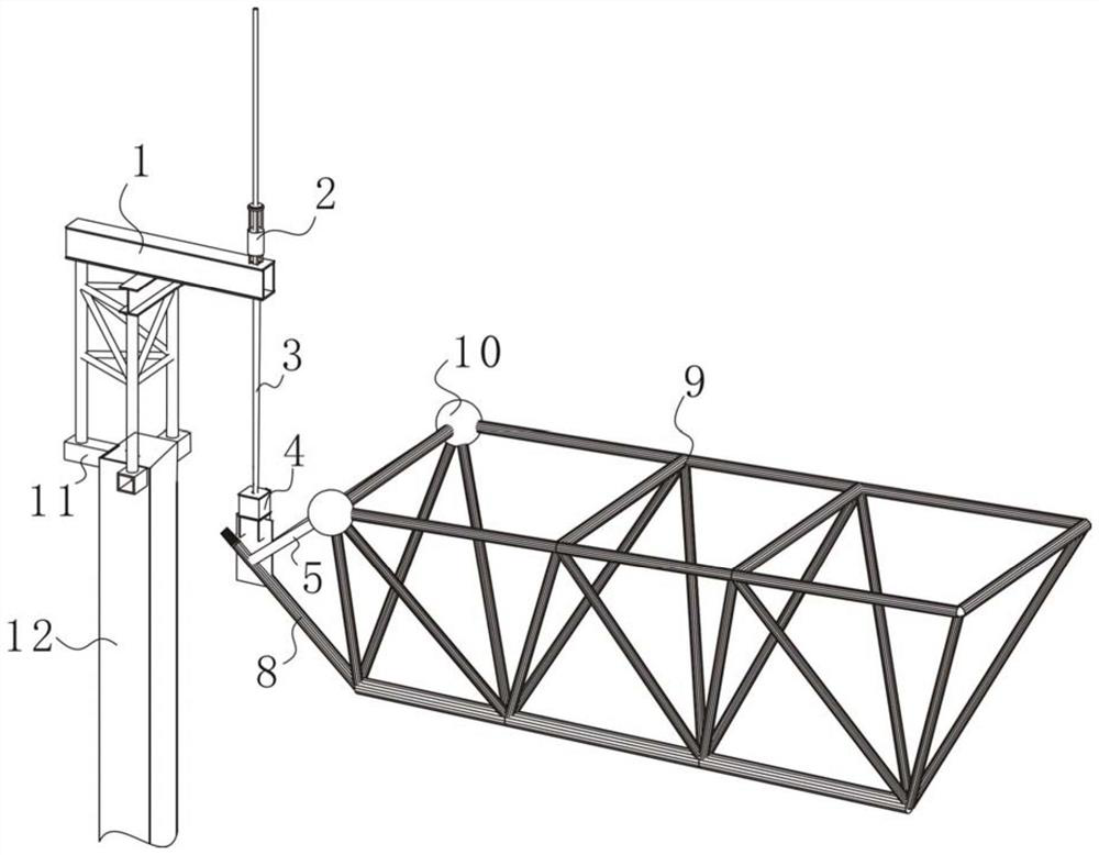
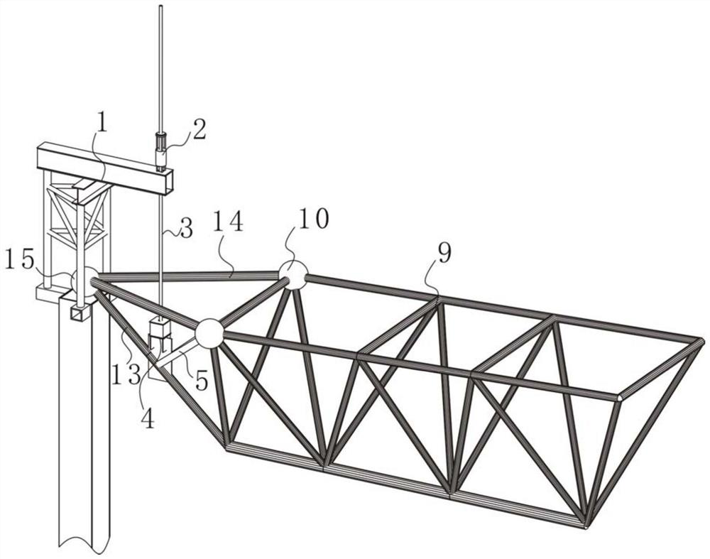
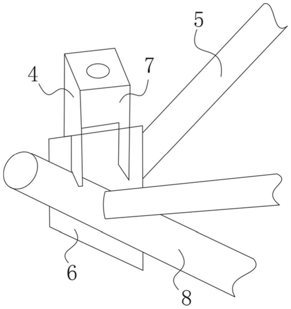
[0026] As shown in the figure, the present invention provides a hoisting device for the lifting point, which is distributed symmetrically around the circumference of the truss 9. The hoisting device includes a lifting bracket 1, a hydraulic lifter 2, a steel strand 3, a hoisting Plate 4 and two sets of connecting rods 5, wherein the lifting bracket 1 is fixed on the corbel 11 on the top of the column 12, the hydraulic lifter 2 is fixed on the lifting bracket 1, the hydraulic lifter 2 pulls the steel strand 3 upward, and the hanging plate 4 It includes a detachably connected flashboard 6 and a hanger 7, the flashboard 6 is vertically inserted into the lower chord 8 outside the truss 9, and the flashboard 6 is fixedly conne...


PUM


Abstract

The invention provides a lower lifting point lifting device and a lower lifting point integrated integral lifting method, and relates to the field of steel structure engineering. The lifting device issymmetrically distributed on the circumference of a truss, and the lower lifting point lifting device comprises a lifting support, a hydraulic lifter, a steel strand, a lifting plate and two sets ofconnecting rods. According to the lower lifting point lifting device and the lower lifting point integrated integral lifting method, the lifting point form is simplified, three temporary rod pieces are omitted, the measure amount of a temporary structure is reduced, a large amount of high-altitude disassembling work after lifting in place is greatly reduced, and the construction period is shortened; and the truss is integrally lifted to the designed elevation, then rod piece welding and two sets of upper chords at the opening alignment position are carried out, the construction amount and construction difficulty of the site high altitude are greatly reduced, and the construction cost is reduced.

Description

technical field [0001] The invention relates to the field of steel structure engineering, in particular to a hoisting point lifting device and a hoisting point integral hoisting method. Background technique [0002] The truss structure is a beam-type member, which is an "open belly beam" composed of multiple small-section rods, and is a statically determinate structure; because its section can be made very high, it has a large bending resistance, and the deflection Smaller, this can be suitable for a larger span than the solid web beam, and it saves materials and has a small dead weight; the truss structure is often used in public buildings such as large-span factories, exhibition halls, gymnasiums and bridges; Structures, trusses are also commonly referred to as roof trusses. [0003] The main body of the truss is usually welded on the ground, and then hoisted in place by hoisting equipment. The traditional method: the structure of the temporary lifting point for conventio...

Claims


Application Information

Patent Timeline
Patent Type & Authority Applications(China)
IPC IPC(8): E04G21/14E04G21/16B66C25/00B66C1/10
CPCB66C1/10B66C25/00E04G21/142E04G21/162
Inventor 勾金旺杨新强朱海森
Owner 天津建工科技有限公司
Learn More