Obstacle positioning method and device based on ultrasonic radars and computer equipment

A positioning method, ultrasonic technology, applied in the field of data processing, can solve the problem of difficult balance between positioning cost and accuracy

Pending Publication Date: 2020-09-29
浙江华消科技有限公司
View PDF8 Cites 4 Cited by
  • Summary
  • Abstract
  • Description
  • Claims
  • Application Information

AI Technical Summary

Problems solved by technology

[0005] The embodiment of the present application provides an ultrasonic radar-based obstacle positioning method, device, computer equipment, and computer-readable stor

Method used


Image

  • Obstacle positioning method and device based on ultrasonic radars and computer equipment
  • Obstacle positioning method and device based on ultrasonic radars and computer equipment
  • Obstacle positioning method and device based on ultrasonic radars and computer equipment

Examples


Embodiment Construction

[0055] In order to make the purpose, technical solutions and advantages of the present application clearer, the present application will be described and illustrated below in conjunction with the accompanying drawings and embodiments. It should be understood that the specific embodiments described here are only used to explain the present application, and are not intended to limit the present application. Based on the embodiments provided in the present application, all other embodiments obtained by persons of ordinary skill in the art without creative efforts shall fall within the protection scope of the present application.

[0056] Obviously, the accompanying drawings in the following description are only some examples or embodiments of the present application, and those skilled in the art can also apply the present application to other similar scenarios. In addition, it can also be understood that although such development efforts may be complex and lengthy, for those of ...


PUM


Abstract

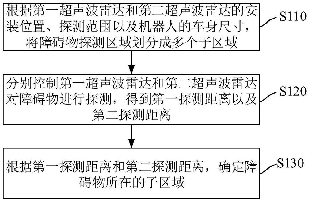
The invention relates to an obstacle positioning method and device based on ultrasonic radars and computer equipment. The obstacle positioning method based on the ultrasonic radars comprises the stepsthat an obstacle detection area is divided into a plurality of subareas according to the installation positions and detection ranges of a first ultrasonic radar and a second ultrasonic radar and thevehicle body size of a robot; the first ultrasonic radar and the second ultrasonic radar are respectively controlled to detect the obstacle to obtain a first detection distance and a second detectiondistance; according to the first detection distance and the second detection distance, the sub-region where the obstacle is located is determined. The problem that cost and precision are difficult toconsider when ultrasonic radars are used for obstacle positioning is solved.

Description

technical field [0001] The present application relates to the technical field of data processing, in particular to an ultrasonic radar-based obstacle location method, device and computer equipment. Background technique [0002] Robots generally use ultrasonic radar for obstacle avoidance, and use one or more ultrasonic radars to measure the distance of obstacles in front of the robot. Due to the wide detection range of the ultrasonic radar, this method can only obtain the distance information of the obstacle, but not the direction information, and can only know the straight-line distance between the robot and the obstacle. Further prior art divides and identifies the area where the obstacle is located, but in the case of a limited number of radars, the divided area is less, and only a rough location of the area can be obtained. There may be situations where there are no obstacles on the robot’s forward path, but there are obstacles beside the forward path that are detected ...

Claims


Application Information

Patent Timeline
IPC IPC(8): G01S15/93G01S15/87
CPCG01S15/93G01S15/87
Inventor 陈高阳华滨吴天桂夏红峰徐耀飞
Owner 浙江华消科技有限公司
Why Eureka
Try Eureka