Medical guide device
A guiding device and mandrel technology, applied in catheters, medical science, balloon catheters, etc., can solve the problems of adjusting the stiffness of the guiding device, which cannot be realized, etc.
- Summary
- Abstract
- Description
- Claims
- Application Information
AI Technical Summary
Problems solved by technology
Method used
Image
Examples
Embodiment 1
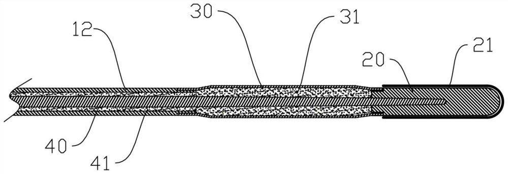
[0054] Such as figure 1 As shown, a medical guiding device of this preferred embodiment includes
[0055] guide body 10, comprising a guide mandrel;
[0056] The head 20 is located at the distal end of the guide body 10;
[0057] The stiffness adjustment part is arranged between the guide body 10 and the head part 20, and changes the local stiffness of the guide device by changing its own stiffness. The stiffness adjustment part is a capsule 30 sealed at both ends;
[0058] Wherein, the stiffness of the stiffness adjusting part can be adjusted by guiding the mandrel or through the pressure channel, and the specific structure and implementation will be described in detail in the following examples.
[0059] The guide body 10 refers to the part of the whole guide device except the head 20 and the stiffness adjustment part at the distal end, and a guide mandrel 40 is arranged inside. The stiffness adjustment part is arranged between the guide body 10 and the head 20, and the s...
Embodiment 3
[0076] In the third embodiment, except that the position of the pressure channel is different from that in the second embodiment, other structures, processing techniques, and materials are the same as those in the second embodiment, and will not be described again.
[0077] Based on the above-mentioned Embodiment 2 and Embodiment 3, for different media 31 control methods, the medical guidance device of this embodiment includes the operation structures of Embodiment 4 and Embodiment 5. Below, Embodiment 4 and Embodiment 1 will be described in detail with reference to the accompanying drawings Five operating structures and modes of operation.
Embodiment 4
[0079] as attached image 3 And attached Figure 4 As shown, the pressure channel 41 in this embodiment is not pre-filled with the medium 31, but filled with the medium 31 during use. Therefore, the guide body 10 includes a hose 12 and a guide mandrel 40, and the guide body 10 The proximal end is provided with a connecting end for connecting a pressure source 50, and the pressure source 50 communicates with the pressure channel 41, and the pressure source 50 fills or sucks the medium 31 into the pressure channel 41 to adjust the medium 31 in the capsule 30 state, the flow rate of the medium 31 in this embodiment is controlled by the pressure source 50 . The proximal end (ie, the operating end) of the guide body 10 is sealingly connected with the end cap of the pressure source 50 , so that the pressure source 50 presses or sucks the medium 31 into the pressure channel 41 . The connection structure between the proximal end of the guide body 10 and the pressure source 50 may be...
PUM
| Property | Measurement | Unit |
|---|---|---|
| Length | aaaaa | aaaaa |
| Length | aaaaa | aaaaa |
| Length | aaaaa | aaaaa |
Abstract
Description
Claims
Application Information
 - R&D
- Intellectual Property
- Life Sciences
- Materials
- Tech Scout
- Unparalleled Data Quality
- Higher Quality Content
- 60% Fewer Hallucinations
Browse by: Latest US Patents, China's latest patents, Technical Efficacy Thesaurus, Application Domain, Technology Topic, Popular Technical Reports.
© 2025 PatSnap. All rights reserved.Legal|Privacy policy|Modern Slavery Act Transparency Statement|Sitemap|About US| Contact US: help@patsnap.com


