
Automobile fan heater pressure chamber plate structure

A technology for automobile heaters and pressure chambers, which is applied to superstructures, subassemblies of superstructures, and vehicle components, and can solve problems such as incomplete electrophoresis, local stiffness, low modal, and easy formation of air pockets, etc. Install quality problems, improve local modes, and weaken the effect of Z-direction strength

Active Publication Date: 2020-10-02
CHONGQING CHANGAN AUTOMOBILE CO LTD
View PDF7 Cites 0 Cited by
  • Summary
  • Abstract
  • Description
  • Claims
  • Application Information

AI Technical Summary

Problems solved by technology

[0004] (1) The front windshield mounting plate and the pressure chamber plate body form a cavity structure similar to the lower opening. When overpainted, it is easy to form air pockets, resulting in incomplete electrophoresis and very easy to cause corrosion of parts;
[0005] (2) In order to meet the pedestrian protection performance, the glass installation surface does not form a closed cavity structure, the local stiffness and mode are very low, and it is easy to generate noise, abnormal sound and other problems
[0008] Undoubtedly, the technical scheme disclosed in the above-mentioned patent documents is a beneficial attempt in the technical field

Method used


Image

  • Automobile fan heater pressure chamber plate structure
  • Automobile fan heater pressure chamber plate structure
  • Automobile fan heater pressure chamber plate structure

Examples


Embodiment Construction

[0036] The present invention will be described in detail below in conjunction with the accompanying drawings.

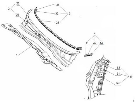
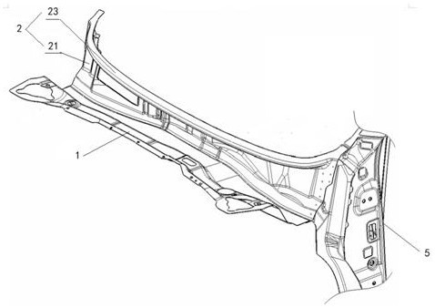
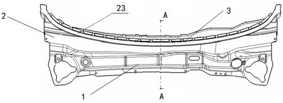
[0037] see Figure 1 to Figure 6 A car heater pressure chamber plate structure shown includes a heater pressure chamber plate assembly, a side wall assembly 5 at the end of the heater pressure chamber plate assembly, and the side wall assembly connects with the connecting member 4 The heater pressure chamber plate assembly connection, its outstanding substantive features are:

[0038] The heater pressure chamber plate assembly includes a pressure chamber front plate 1, a pressure chamber rear plate 2 whose lower edge is overlapped with the rear edge of the pressure chamber front plate; the pressure chamber rear plate 2 has a rear plate facade 21, Rear panel slope 22, backward curved surface and front windshield mounting surface 23;

[0039] The heater pressure chamber plate assembly also includes a reinforcing member 3, the reinforcing member 3 has a "["-shaped cro...


PUM


Abstract

The invention relates to an automobile fan heater pressure chamber plate structure which comprises a fan heater pressure chamber plate assembly and a side wall assembly connected with the end of the fan heater pressure chamber plate assembly. The side wall assembly is connected with the fan heater pressure chamber plate assembly through a connecting component. The fan heater pressure chamber plateassembly comprises a pressure chamber front plate and a pressure chamber rear plate, wherein the lower edge of the pressure chamber rear plate is fixedly overlapped with the rear edge of the pressurechamber front plate; the pressure chamber rear plate is provided with a rear plate vertical surface, a rear plate inclined surface, a curved surface bent backwards and a front windshield mounting surface which are connected in sequence. The fan heater pressure chamber plate assembly further comprises a reinforcer, the section of the reinforcer is in a [ shape, and the reinforcer is provided witha bottom face, a lower side turning face and an upper side face. The reinforcer is matched and connected with the upper part of the rear surface of the pressure chamber rear plate to form a closed cavity structure, and the cavity structure and the vertical surface of the rear plate form a cantilever structure. The corrosion resistance of the pressure chamber plate structure of the automobile fan heater can be improved, the strength and rigidity are improved, the NVH performance is improved, and the pedestrian protection requirement can be met.

Description

technical field [0001] The invention relates to an automobile body, in particular to a pressure chamber plate structure of an automobile heater. Background technique [0002] With the development of automobile technology, automobile design has begun to change from structural design to performance design. Some problems such as rust, abnormal noise, and noise have become problems that many OEMs need to solve urgently. The pressure chamber plate assembly of the automobile heater is located at the lower part of the front windshield, and is an important part connecting the left and right side panels and isolating the engine room and the passenger compartment. It has an important impact on the torsional stiffness and modal of the car body, and it is the main drainage structure of the front car body. The environment is relatively harsh. If the structure is unreasonable, it will easily cause parts corrosion, abnormal noise, noise, etc., which will affect the quality and quality of t...

Claims


Application Information

Patent Timeline
IPC IPC(8): B62D25/02B62D25/08B60H1/00B60R13/08
CPCB62D25/02B62D25/08B60H1/00507B60R13/08
Inventor 王平黄川韩常青
Owner CHONGQING CHANGAN AUTOMOBILE CO LTD
Learn More