
Tubing head and casing head device for oil development and using method thereof

A technology of tubing head and casing head, which is applied in the field of components for petroleum development, can solve the problems of difficulty in adjusting the length of the four-way connection, heavy tubing, and large human factors, and achieves low cost, simplified operation, and improved safety. Effect

Active Publication Date: 2020-10-02
PUYANG HAIHUA GASOLINEEUM MACHINERY
View PDF9 Cites 1 Cited by
  • Summary
  • Abstract
  • Description
  • Claims
  • Application Information

AI Technical Summary

Problems solved by technology

[0003] However, in the traditional tubing suspension method, the casing head body is connected with the casing through threaded connection, and then the tubing is connected with the hanger through the threaded connection method, and then the hanger is connected with the casing head body to realize suspension, fixation and sealing. , since the oil pipe 1 generally has a dead weight of 30 tons to 150 tons, and then when the oil pipe 1 is not centered and the inside of the casing is eccentric, it is very difficult to adjust. The set rope cannot be positioned, so two sets of ropes are needed. When pulling with the rope, you need to solve the problem of direction, the fixing of the other end of the rope, the size of the pulling force, the size of the space and the safety problem. The solution to these problems requires experience, equipment and time. The human factor is relatively large, and the connection length of the traditional cross is difficult to adjust. Therefore, when the cross is connected to the parts to be connected, such as the oil pipe at the oil well head, the oil pipe at the oil well head is usually longer and heavier. Thereby it is difficult to make the nozzle of the oil pipe at the oil wellhead fit the nozzle of the four-way by pulling the oil pipe at the oil wellhead

Method used


Image

  • Tubing head and casing head device for oil development and using method thereof
  • Tubing head and casing head device for oil development and using method thereof
  • Tubing head and casing head device for oil development and using method thereof

Examples


Embodiment Construction

[0034] The following will clearly and completely describe the technical solutions in the embodiments of the present invention with reference to the accompanying drawings in the embodiments of the present invention. Obviously, the described embodiments are only some, not all, embodiments of the present invention. Based on the embodiments of the present invention, all other embodiments obtained by persons of ordinary skill in the art without making creative efforts belong to the protection scope of the present invention.

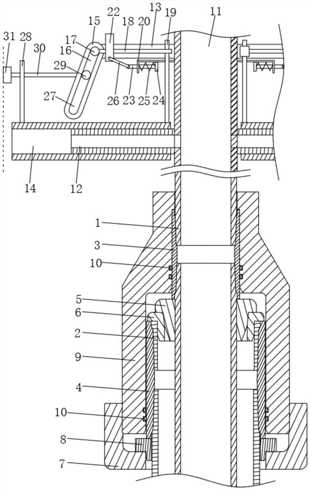
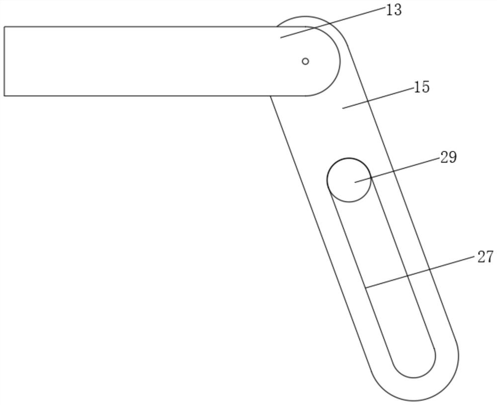
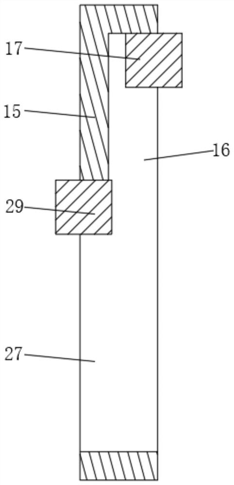
[0035] see Figure 1 to Figure 6 , the present invention provides a technical solution: a tubing head and casing head device for oil development, including a cross, and a hanger for hanging tubing-1 and casing-2, the hanger includes a tubing-1 The inner collar 3 connected with 1 and the outer collar 4 used for the connection of the casing one 2, and the inner positioning sleeve 5 and the outer positioning sleeve 6 arranged between the tubing one 1 and the casi...


PUM


Abstract

The invention discloses a tubing head and casing head device for oil development, and relates to the technical field of oil development devices. A hanger comprises an inner-layer coupling for being connected with first tubing and an outer-layer coupling for being connected with a first casing, and further comprises an inner positioning sleeve and an outer positioning sleeve which are arranged between the first tubing and the first casing, a locking mechanism, a slip and a sealing shell are sequentially connected to the outer wall from the first tubing to the first casing in a series mode, a sealing assembly is arranged in the sealing shell, a four-way joint comprises a main tube body connected with the first tubing, and four branch tube bodies fixedly communicating with the main tube body,and connecting length adjusting mechanisms connected with a to-be-connected part are arranged on the four branch tube bodies correspondingly. Through cooperation between the structures, on the one hand, the connecting length of the four-way joint is convenient to adjust, on the other hand, the hanger can automatically adjust the position of the first tubing and the first casing, so that the firsttubing and the first casing are centered and concentric.

Description

technical field [0001] The invention relates to the technical field of components for petroleum development, in particular to an oil pipe head and casing head device for petroleum development. Background technique [0002] The tubing head is a device that connects the uppermost casing head and the Christmas tree to hang the tubing and the casing. The tubing head is located on the casing head, including the cross and the hanger. Its function is to hang the tubing, downhole tools, casing. [0003] However, in the traditional tubing suspension method, the casing head body is connected with the casing through threaded connection, and then the tubing is connected with the hanger through the threaded connection method, and then the hanger is connected with the casing head body to realize suspension, fixation and sealing. , since the oil pipe 1 generally has a dead weight of 30 tons to 150 tons, and then when the oil pipe 1 is not centered and the inside of the casing is eccentric...

Claims


Application Information

Patent Timeline
IPC IPC(8): E21B33/047E21B33/04
CPCE21B33/047E21B33/0422E21B33/04
Inventor 赵会涛管方龙彭艳敏谢彦甫管庆先王安强何瑞雪
Owner PUYANG HAIHUA GASOLINEEUM MACHINERY
Learn More