A bionic sucker

A technology of suction cups and vacuum generators, which is applied in the direction of suction cups, connecting components, conveyor objects, etc., can solve problems such as leakage, failure to meet work requirements, and reduced adsorption performance, so as to enhance applicability, improve anti-interference ability, and improve Effects on Crawl Performance

Active Publication Date: 2022-04-01
HOHAI UNIV CHANGZHOU
View PDF17 Cites 0 Cited by
  • Summary
  • Abstract
  • Description
  • Claims
  • Application Information

AI Technical Summary

Problems solved by technology

[0003] Aiming at the deficiencies of the prior art, the purpose of the present invention is to provide a bionic suction cup to solve the problem that the vacuum suction cup with the traditional structure in the prior art tends to leak when it absorbs and grabs the target with poor surface quality, which leads to poor adsorption performance. Reduce technical issues that often fail to meet job demands

Method used


Image

  • A bionic sucker
  • A bionic sucker
  • A bionic sucker

Examples


Embodiment Construction

[0023] The present invention will be further described below in conjunction with the accompanying drawings. The following examples are only used to illustrate the technical solution of the present invention more clearly, but not to limit the protection scope of the present invention.

[0024] It should be noted that, in the description of the present invention, the terms "front", "rear", "left", "right", "upper", "lower", "inner", "outer" and the like indicate orientations or positions The relationship is based on the orientation or positional relationship shown in the drawings, and is only for the convenience of describing the present invention and does not require that the present invention must be constructed and operated in a specific orientation, and thus should not be construed as a limitation of the present invention. The terms "front", "rear", "left", "right", "upper" and "lower" used in the description of the present invention refer to the directions in the drawings, ...


PUM


Abstract

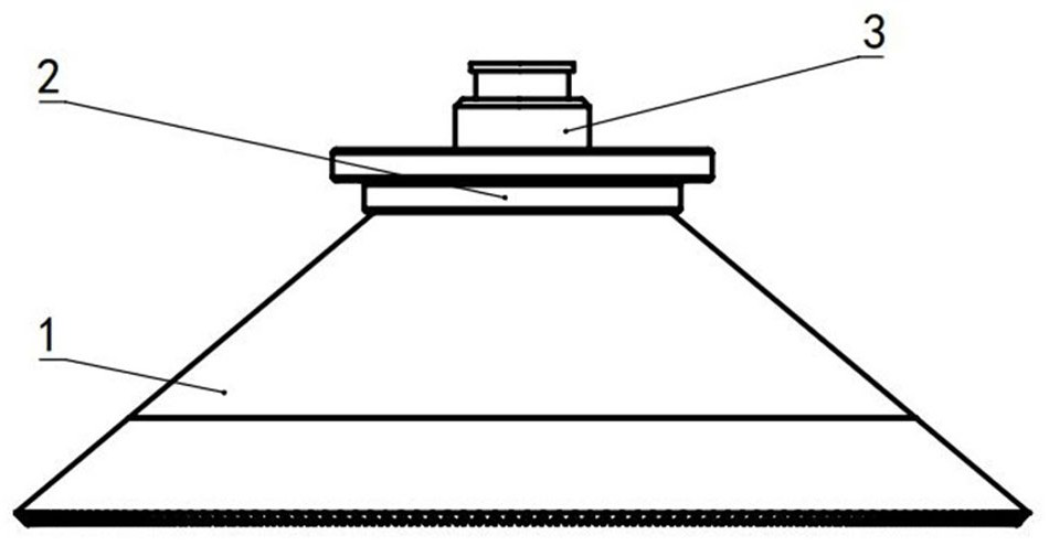
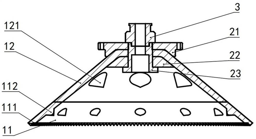
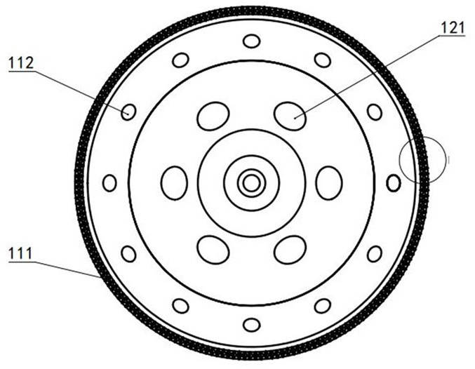
The invention discloses a bionic suction cup in the technical field of suction cup grabbing, aiming to solve the problem that the vacuum suction cup with the traditional structure in the prior art is prone to leakage when absorbing and grabbing targets with poor surface quality, resulting in a decrease in adsorption performance. Technical issues that often do not meet the needs of the job. The suction cup includes a suction cup main body, the side wall of the suction cup main body gradually becomes thinner from the top to the bottom, the top of the suction cup main body is provided with a first through hole, the bottom outer edge of the suction cup main body is provided with a protrusion, and the inner surface of the suction cup main body With hard teeth.

Description

technical field [0001] The invention relates to a bionic sucker, which belongs to the technical field of sucker grasping. Background technique [0002] Due to the excellent characteristics of fast response, stable adsorption and no damage to the surface of objects, vacuum suction cups have become more and more widely used in daily life and industrial production in recent years, especially in fragile products, flat parts, etc. that are not suitable for traditional manipulators. In application scenarios, it plays an irreplaceable role. However, in the actual working scene, the surface of the grasped part often has certain roughness or undulations, such as cardboard, wood and other surface of the grasped part may also have air holes, grooves and other undulating structures, which will damage the edge of the suction cup and the grasped part. The sealing structure formed on the surface. Vacuum suction cups with traditional structure will leak when absorbing and grabbing targets...

Claims


Application Information

Patent Timeline
Patent Type & Authority Patents(China)
IPC IPC(8): F16B47/00B65G47/91
CPCF16B47/00B65G47/91
Inventor 王延杰张宇霆杨志威徐望舒骆敏舟朱灯林
Owner HOHAI UNIV CHANGZHOU
Why Eureka
Try Eureka