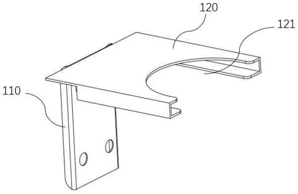
Cup clamping device

A cup and gap technology is applied in the field of cup gripping devices, which can solve the problems of cup shape inconsistency, overall cost increase, rupture, etc., and achieve the effects of reducing the amount of wiring engineering, low manufacturing cost, and fast production speed.

Inactive Publication Date: 2020-10-02
北京鸿霁科技有限公司
View PDF12 Cites 0 Cited by
  • Summary
  • Abstract
  • Description
  • Claims
  • Application Information

AI Technical Summary

Problems solved by technology

If the stroke is not adjusted properly, or the shape of the clamp arm does not match the shape of the cup, it is easy to cause the cup body to sag or break
The control of the motor increases the amount of programming and wiring engineering in the application scenario, resulting in an increase in the overall cost
[0004] The patent application document with the application number 201020165887.7 discloses a high-temperature beaker gripper, which consists of two opposite petioles and hinged petioles. Although the structure is simple, it is necessary to realize the separation of the two petioles during the automatic operation of the gripper. and merging operations, and it is necessary to accurately locate the placement position of the cup, and the automatic grasping operation still requires a complex mechanical structure to drive
[0005] The patent application document with the application number 201710715691.7 discloses a paper cup grabbing and collecting device, which includes a guide mechanism and gripping claws. The clamping device is driven by the cylinder and the gripping claws. Although the cost of manual operation is reduced, the mechanical structure is complicated. , the operation steps are cumbersome
[0006] The application number is 201820553152.8, which discloses an integrated device for detecting and grasping cups, which realizes the clamping and fixing of the cup body through two claws, and sets two microcontrollers in the claws. Although the structure is simplified, there is no need to use photoelectric sensors to detect cups However, it is still necessary to set two microcontrollers in the claw valve. When the cup is filled with liquid, there is still the possibility of spilling, which is easy to damage the controller, resulting in high maintenance costs and poor specific application effects.

Method used


Image

  • Cup clamping device
  • Cup clamping device
  • Cup clamping device

Examples


Embodiment Construction

[0033] The implementation mode of the present invention is illustrated by specific specific examples below, and those who are familiar with this technology can easily understand other advantages and effects of the present invention from the contents disclosed in this description. Obviously, the described embodiments are a part of the present invention. , but not all examples. Based on the embodiments of the present invention, all other embodiments obtained by persons of ordinary skill in the art without making creative efforts belong to the protection scope of the present invention.

[0034] It should be noted that, in the description of the present invention, terms such as "middle", "upper", "lower", "horizontal", "inner" and other indicated directions or positional relationships are based on the directions or positional relationships shown in the drawings. The positional relationship, which is just for convenience of description, does not indicate or imply that the device or...


PUM


Abstract

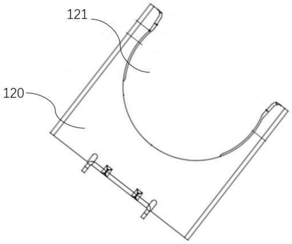
The invention belongs to the technical field of machinery, and discloses a cup clamping device which comprises a detachable fixing part, which is detachably connected with a clamping driving table; and a clamping part, wherein one end of the clamping part is hinged to the detachable fixing part, and the other end of the clamping part is provided with a notch, which can be arranged outside a cup ina sleeving mode and can drive the cup to move. The clamping part is a circular or square plate with the notch. Auxiliary bending protection plates are arranged on the two sides of the clamping part and integrally connected with the clamping part. The cup clamping device is low in cost, free of power, self adaptive, free of power drive and program control and easy to machine, install and use.

Description

technical field [0001] The invention relates to the technical field of machinery, in particular to a cup clamping device. Background technique [0002] Most of the existing cup grabbing jaws simulate the action of human hands. The cup grabbing action is completed through two or more gripper arms, bases, motors and transmission mechanisms, and a controller is required to complete the action control. Commonly used in unmanned coffee machines, automatic beverage or ice cream vending machines. [0003] When grabbing cups of different sizes, types, and materials, it is necessary to adjust the stroke or shape of the jig arm to adapt, or add a pressure sensor to the jig arm to feedback whether the object is caught. If the stroke is not adjusted properly, or the shape of the clamp arm does not match the shape of the cup, the cup body will be easily dented or broken. The control of the motor increases the amount of programming and wiring engineering in the application scenario, res...

Claims


Application Information

Patent Timeline
Patent Type & Authority Applications(China)
IPC IPC(8): G07F13/10
CPCG07F13/10
Inventor 蒋志亮
Owner 北京鸿霁科技有限公司
Why Eureka
Try Eureka