Heating system of continuous annealing wire drawing machine

A technology of heating system and wire drawing machine, applied in the field of continuous annealing wire drawing machine, which can solve the problems that the temperature is difficult to be fully utilized, the drawing tension is inconvenient to adjust, and the position of the steel wire is easy to change during transmission, so as to achieve the change of tension degree and simple operation , Ease of use

Inactive Publication Date: 2020-10-09
王小珍
View PDF0 Cites 5 Cited by
  • Summary
  • Abstract
  • Description
  • Claims
  • Application Information

AI Technical Summary

Problems solved by technology

[0004] The purpose of the present invention is to solve the disadvantages that the existing continuous annealing wire drawing machine is difficult to fully utilize the temperature during wire drawing, and the tension during wire drawing is inconvenient to adjust, and the position of the steel wire is easy to change during transmission, resulting in unstable heating. A heating system for a continuous annealing wire drawing machine

Method used


Image

  • Heating system of continuous annealing wire drawing machine
  • Heating system of continuous annealing wire drawing machine
  • Heating system of continuous annealing wire drawing machine

Examples


Embodiment 1

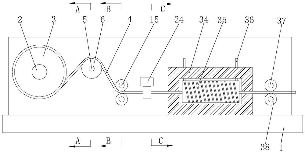
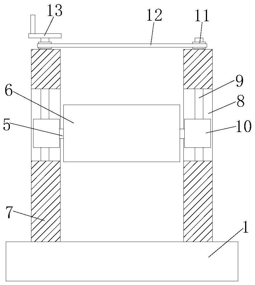
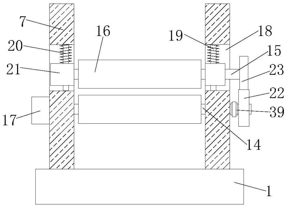
[0029] refer to Figure 1-5 , a heating system for a continuous annealing wire drawing machine, comprising a base 1, two symmetrically arranged support plates 7 are fixedly installed on the top of the base 1, and a first rotating shaft 2 is rotationally connected to the two supporting plates 7, and the first rotating shaft 2 The outer fixed sleeve is provided with a pay-off roller 3, and the outer side of the pay-off roller 3 is wound with a copper wire 4, and the second rotating shaft 5 is rotatably connected to the two support plates 7, and the outer fixed sleeve of the second rotating shaft 5 is provided with a tension roller 6 A third rotating shaft 14 and a third rotating shaft 14 are rotatably connected to the two support plates 7, and the outer sides of the third rotating shaft 14 and the fourth rotating shaft 15 are fixedly sleeved with guide rollers 16, and are fixedly installed between the two support plates 7. On the same fixed plate 24, two symmetrical clamping blo...

Embodiment 2

[0040] refer to Figure 1-5 , a heating system for a continuous annealing wire drawing machine, including a base 1, two symmetrically arranged support plates 7 are welded on the top of the base 1, and a first rotating shaft 2 is rotatably connected to the two supporting plates 7, and the outer side of the first rotating shaft 2 The fixed sleeve is provided with a pay-off roller 3, the outer side of the pay-off roller 3 is provided with a copper wire 4, the second rotating shaft 5 is rotatably connected to the two support plates 7, and the outer fixed sleeve of the second rotating shaft 5 is provided with a tension roller 6, The third rotating shaft 14 and the third rotating shaft 14 are rotatably connected to the two supporting plates 7, and the outer sides of the third rotating shaft 14 and the fourth rotating shaft 15 are fixedly sleeved with guide rollers 16, and the two supporting plates 7 are welded with the same The fixed plate 24 is slidably connected with two symmetric...


PUM


Abstract

The invention belongs to the technical field of continuous annealing wire drawing machines, particularly relates to a heating system of a continuous annealing wire drawing machine, and aims to solve the problems that the temperature of the existing continuous annealing wire drawing machine is difficult to fully utilize during wire drawing, the tension during wire drawing is inconvenient to adjust,the position of a steel wire is easy to change during conveying, and the heating is unstable. According to the scheme, the heating system of the continuous annealing wire drawing machine comprises abase, two symmetrically-arranged supporting plates are fixedly installed at the top of the base, a first rotating shaft is rotationally connected to the two supporting plates, the outer side of the first rotating shaft is fixedly sleeved with a pay-off roller, and the outer side of the pay-off roller is wound with a copper wire; and a second rotating shaft is rotationally connected to the two supporting plates, the outer side of the second rotating shaft is fixedly sleeved with a tension roller, and the two supporting plates are rotationally connected with a third rotating shaft and a fourth rotating shaft. The heating system is easy to operate and convenient to use, can heat and stretch the copper wire, can change the tension of the copper wire, can position the position state of the copper wire, and is convenient for people to use.

Description

technical field [0001] The invention relates to the technical field of continuous annealing wire drawing machines, in particular to a heating system for continuous annealing wire drawing machines. Background technique [0002] The continuous annealing wire drawing machine is based on the original wire drawing machine plus online annealing, and the product is formed at one time to improve the production efficiency. It is mainly used in the copper wire drawing industry, brass wire drawing machine industry, aluminum wire drawing industry, copper clad copper wire This type of equipment can be used in the drawing of non-ferrous metals such as the wire drawing industry. The catalog is not yet mature for the application of such equipment in the drawing of ferrous metals such as copper wire. [0003] The existing continuous annealing wire drawing machine is difficult to fully utilize the temperature during wire drawing, and it is inconvenient to adjust the tension during wire drawin...

Claims


Application Information

Patent Timeline
Patent Type & Authority Applications(China)
IPC IPC(8): B21C1/02B21C1/12B21C1/14B21C9/00
CPCB21C1/02B21C1/12B21C1/14B21C9/00
Inventor 王小珍
Owner 王小珍
Why Eureka
Try Eureka