
Quantitative casting overflow device

An overflow device and overflow cup technology, which is applied in the direction of casting molds, casting mold components, casting molding equipment, etc., can solve the problems of poor air permeability of the sand mold upper box, increase the risk of equipment failure, increase casting defects, etc., and reduce molding labor strength, reducing the risk of shrinkage and reducing the height of the box

Pending Publication Date: 2020-10-09
龙岩市龙象机械设备制造有限公司
View PDF0 Cites 2 Cited by
  • Summary
  • Abstract
  • Description
  • Claims
  • Application Information

AI Technical Summary

Problems solved by technology

[0003] There are three main problems in the current production: 1. In order to meet the requirements of discharging molten metal and ensuring the feeding capacity of the riser, the height of the upper box of the sand mold must be high enough, resulting in poor air permeability of the upper box of the sand mold, increasing the risk of poor casting, and also Resulting in a large workload of operators and low production efficiency; 2. The riser casting liquid enters the cavity from the casting port, and the liquid is discharged from the gas and riser to the ground. There is a high-temperature metal solution flowing everywhere in the production area, which will affect production. Environment, easy to cause fire, burns and other personal safety and production safety accidents, increase the risk of equipment failure, and it is difficult to recycle the overflow liquid; 3. The operator cannot confirm the overflow of the metal solution, so that the process stability of the pouring process cannot be guaranteed The casting flow rate is judged by experience, resulting in a certain difference in the performance of multiple products

Method used


Image

  • Quantitative casting overflow device
  • Quantitative casting overflow device

Examples


Embodiment Construction

[0017] In order to make the object and technical solutions of the present invention clearer, the present invention will be further described below in conjunction with the accompanying drawings and embodiments:

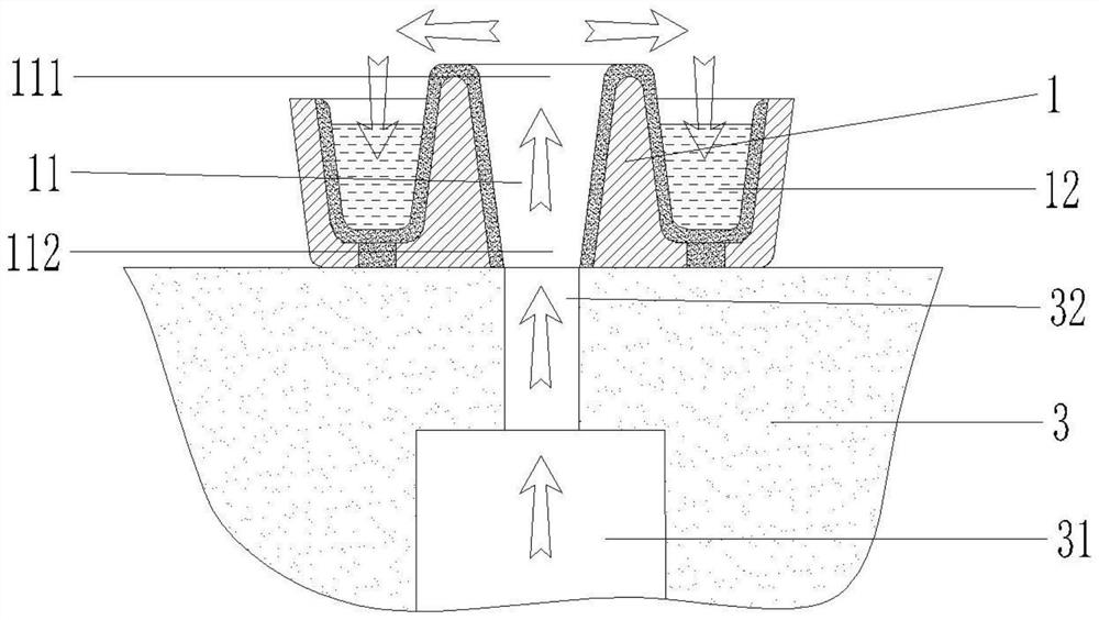
[0018] Such as Figure 1 ~ Figure 2 A quantitative casting overflow device shown includes.

[0019] A quantitative casting overflow device, including a cup holder 1; an overflow channel 11, which runs through the cup holder 1 in a vertical direction, and is arranged at the center of the cup holder 1; an overflow cup 12, located on the cup holder 1 , is an annular groove formed around the overflow channel 11, which is in a basin-like structure; the upper opening 121 of the overflow cup is lower than the upper opening 111 of the overflow channel; the stripping port 122 is arranged on the The bottom of the overflow cup 12 runs through the cup holder 1 .

[0020] Preferably, the cup holder 1 is made of metal; the inner surface of the cup holder 1 is coated with a coating...


PUM


Abstract

The invention provides a quantitative casting overflow device. The quantitative casting overflow device comprises a cup holder, an overflow channel, an overflow cup and a stripping opening, wherein the overflow channel penetrates through the cup holder in the vertical direction and is arranged at the center position of the cup holder; the overflow cup is located on the cup holder, is an annular groove formed by the overflow channel through surrounding and is of a basin-like structure; an upper opening of the overflow cup is lower than an upper opening of the overflow channel; and the strippingopening is formed in the bottom of the overflow cup and penetrates through the cup holder. According to the quantitative casting overflow device, an overflow solution is collected to enable the production to be safe and clean, due to the existence of the overflow channel, the liquid pressure of a gas port and a riser is increased, the density of the casting is improved, the risk of shrinkage porosity of the casting is reduced, the height of box feeding is reduced, the air permeability of a sand mold is improved, and the modeling efficiency is improved; and by observing the overflow of a metalsolution, the overflow weight of the metal solution is set through the process calculation, a quantitative overflow cup suitable for the casting process is designed, and the operating standards of the casting process is formulated and implemented, so that the process is standardized, and the process is visualized.

Description

technical field [0001] The invention relates to a quantitative casting overflow device. Background technique [0002] In the casting process, it is required to exhaust the slag and feed the riser during the filling process of the metal solution, and the metal solution that first enters the mold during the pouring process will cause air holes, slag holes, etc. due to factors such as temperature loss and metal oxidation. The risk of poor casting such as sand hole concentration and loss of feeding ability is extremely high, so the metal solution at the front end of the mold filling is generally discharged from the cavity through the gas and riser. [0003] There are three main problems in the current production: 1. In order to meet the requirements of discharging molten metal and ensuring the feeding capacity of the riser, the height of the upper box of the sand mold must be high enough, resulting in poor air permeability of the upper box of the sand mold, increasing the risk o...

Claims


Application Information

Patent Timeline
IPC IPC(8): B22C9/08B22C9/02
CPCB22C9/02B22C9/088
Inventor 修海涛
Owner 龙岩市龙象机械设备制造有限公司
Learn More