
Electric power system and control method therefor

A power system and relay control technology, applied to batteries, circuits, collectors, etc., can solve problems such as time increase and pre-charging time increase

Active Publication Date: 2020-10-09
TOYOTA JIDOSHA KK
View PDF8 Cites 0 Cited by
  • Summary
  • Abstract
  • Description
  • Claims
  • Application Information

AI Technical Summary

Problems solved by technology

[0004] However, if the smoothing capacitor of the high-voltage auxiliary equipment is precharged in addition to the smoothing capacitor for the secondary battery when the power system is started, the time for precharging will increase.
Therefore, the time from when the driver starts the vehicle to when the drive motor can be driven increases.

Method used


Image

  • Electric power system and control method therefor
  • Electric power system and control method therefor
  • Electric power system and control method therefor

Examples


Embodiment approach

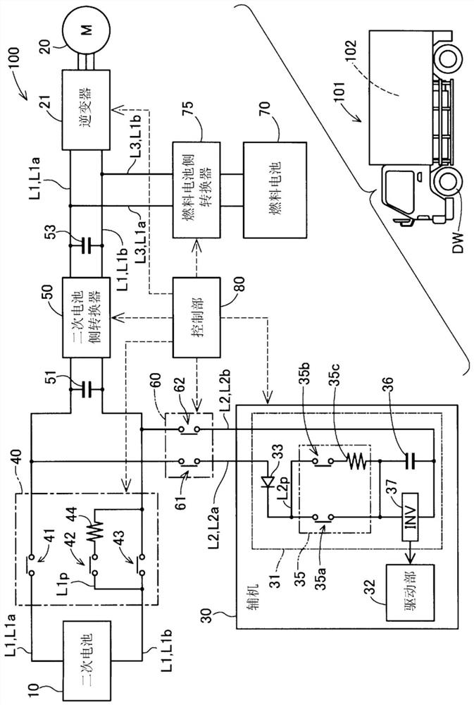
[0018] figure 1 It is a schematic diagram showing the structure of the electric power system 100 in this embodiment. The electric power system 100 is mounted on a vehicle 101 . The power system 100 includes a secondary battery 10 , and supplies electric power from the secondary battery 10 to a drive motor 20 that generates driving force of the vehicle 101 and an auxiliary machine 30 used by the vehicle 101 . However, the vehicle 101 of the present embodiment is a fuel cell vehicle, and the drive motor 20 is driven using the output power of the secondary battery 10 and the output power of the fuel cell 70 as will be described later.

[0019] As the secondary battery 10, for example, a lithium ion battery can be used. The secondary battery 10 is connected to the first DC line L1. The first DC conductor L1 includes a first high-voltage-side conductor L1a connected to the positive-side terminal of the secondary battery 10 and a first low-voltage-side conductor L1b connected to ...

Embodiment approach 1

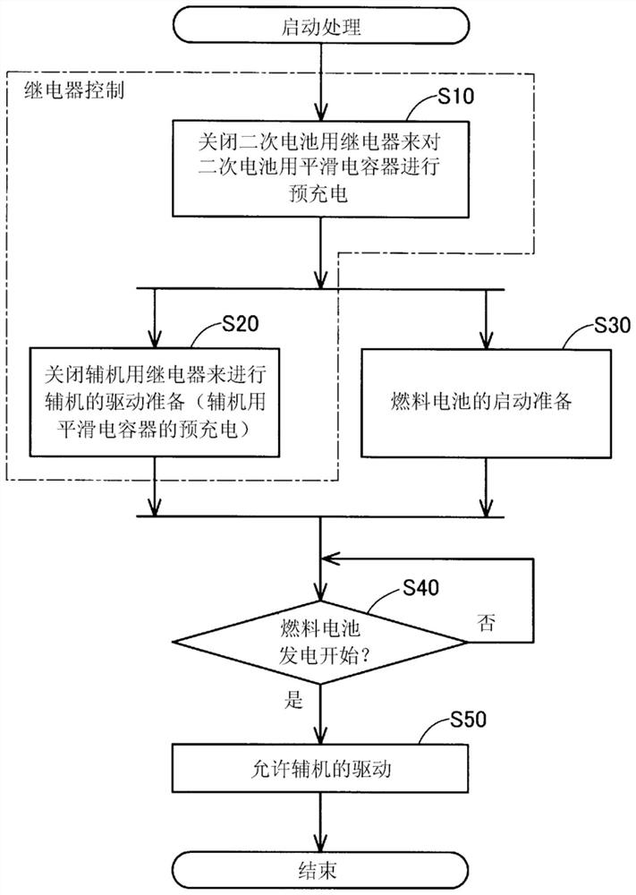
[0056] In the above-described embodiment, the power system 100 may be provided with a power generation device other than the fuel cell 70 instead of the fuel cell 70 . The power system 100 may include, for example, a power generation device that generates power with an internal combustion engine, and a solar panel as a power generation device that generates power to be supplied to the drive motor 20 . In addition, the power system 100 may not include such a power generating device, and may be configured to drive the drive motor 20 and the auxiliary machine 30 using only the power of the secondary battery 10 charged by external power supply. In the startup process of the electric power system 100, steps S30 and S40 can be omitted.

Embodiment approach 2

[0058] In the above embodiments, the auxiliary machine 30 may not be a refrigerator. The auxiliary machine 30 may be constituted by other devices driven by various high voltages, and may be constituted by heavy equipment such as a crane, for example. In addition, the power system 100 may be connected to a plurality of auxiliary machines 30 .


PUM


Abstract

The invention relates to an electric power system and a control method therefor. The electric power system includes a secondary battery configured to supply electric power to a drive motor, configuredto generate driving force of a vehicle, and an auxiliary having an auxiliary smoothing capacitor, a secondary battery relay configured to open or close an electrical contact between the secondary battery and the drive motor, a secondary battery smoothing capacitor connected between the secondary battery relay and the drive motor, an auxiliary relay configured to open or close an electrical contact between the secondary battery and the auxiliary, and a control unit configured to control a switching operation of each of the secondary battery relay and the auxiliary relay. The control unit is configured to, at startup of the vehicle, precharge the secondary battery smoothing capacitor by closing the secondary battery relay and then precharge the auxiliary smoothing capacitor by closing the auxiliary relay.

Description

technical field [0001] The present disclosure relates to a power system and a control method thereof. Background technique [0002] A vehicle that uses a drive motor as a drive force source is generally equipped with an electric system that supplies electric power to the drive motor and various other auxiliary machines. For example, Japanese Patent Laid-Open No. 2008-084628 discloses an electric power system that supplies electric power from a fuel cell and a secondary battery to a drive motor and auxiliary machines. In the power system disclosed in JP 2008-084628, a smoothing capacitor is connected to the secondary battery in order to moderate fluctuations in the output voltage of the secondary battery. In the electric power system disclosed in JP 2008-084628, precharging of the smoothing capacitor for the secondary battery is performed in order to suppress a surge current from flowing to the smoothing capacitor for the secondary battery at the time of startup. [0003] A...

Claims


Application Information

Patent Timeline
Patent Type & Authority Applications(China)
IPC IPC(8): B60L50/75B60L1/00
CPCB60L50/75B60L1/00H01M16/006H01M8/04302H02J1/102H02J2300/30H02J2310/48H02J7/345H02J2207/50Y02E60/10Y02E60/50Y02T10/70Y02T90/40H01M2220/20H01M10/4264B60W10/08
Inventor 小川朋宏马屋原健司川口亮太冈田翔太
Owner TOYOTA JIDOSHA KK
Features
  • Generate Ideas
  • Intellectual Property
  • Life Sciences
  • Materials
  • Tech Scout
  • Unparalleled Data Quality
  • Higher Quality Content
  • 60% Fewer Hallucinations
Learn More