
Trailing edge jet-propelled vector propulsion deformable wing

A vector propulsion and deformable wing technology, applied in the field of aircraft wings, can solve the problems of insufficient improvement of aerodynamic efficiency and flight performance, and achieve the effect of improving aerodynamic efficiency

Pending Publication Date: 2020-10-09
GUANGDONG INST OF AERONAUTICS & ASTRONAUTICS EQUIP & TECH
View PDF0 Cites 2 Cited by
  • Summary
  • Abstract
  • Description
  • Claims
  • Application Information

AI Technical Summary

Problems solved by technology

[0004] Based on this, it is necessary to address the problems of insufficient aerodynamic efficiency and flight performance improvement in the current deformable wing technology, based on the concept of flight-engine integration design, to provide a trailing edge jet vector propulsion deformable wing

Method used


Image

  • Trailing edge jet-propelled vector propulsion deformable wing
  • Trailing edge jet-propelled vector propulsion deformable wing
  • Trailing edge jet-propelled vector propulsion deformable wing

Examples


Embodiment Construction

[0027] In order to make the object, technical solution and advantages of the present invention clearer, the present invention will be further described in detail through the following embodiments and in conjunction with the accompanying drawings. It should be understood that the specific embodiments described here are only used to explain the present invention, not to limit the present invention.

[0028] The serial numbers assigned to the components in this document, such as "first", "second", etc., are only used to distinguish the described objects and do not have any sequence or technical meaning. The "connection" and "connection" mentioned in this application all include direct and indirect connection (connection) unless otherwise specified. In describing the present invention, it is to be understood that the terms "upper", "lower", "front", "rear", "left", "right", "vertical", "horizontal", "top", The orientation or positional relationship indicated by "bottom", "inner",...


PUM


Abstract

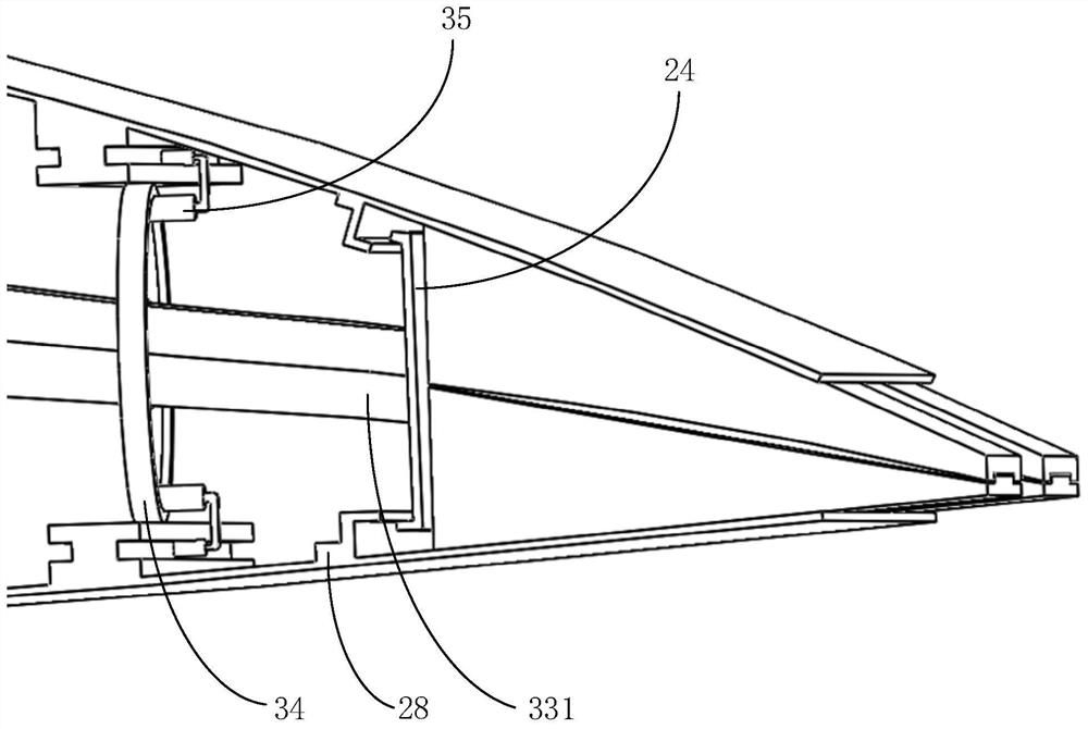
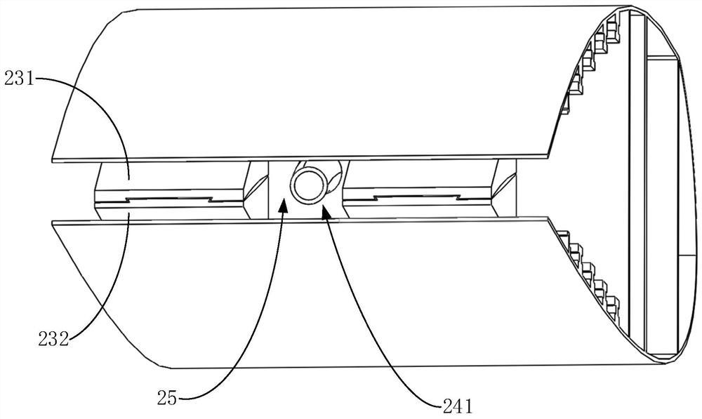
The invention provides a trailing edge jet-propelled vector propelling deformable wing. The deformable wing comprises a rigid box section, an elastic box section and a driving mechanism. A pipeline arranged in the rigid box section can conduct high-pressure airflow generated by an aircraft engine to a driving mechanism distributed in the wing elastic box section; a hollow bent pipe of the drivingmechanism can conduct high-pressure airflow to the rear edge of the wing, and the high-pressure airflow is sprayed out from the rear edge of the wing at different angles to generate thrust, so that the purpose of distributed vector propulsion is achieved. Meanwhile, the driving mechanism can drive the elastic box section to deform, the wing form is changed, and the aerodynamic efficiency, stall attack angle limit, lift coefficient and flight performance are improved.

Description

technical field [0001] The invention relates to the technical field of aircraft wings, in particular to a trailing edge jet vector propulsion deformable wing. Background technique [0002] Both manned and unmanned aerial vehicles are widely used in military and civilian fields. The aircraft mainly relies on the wing to generate lift in the directional air flow field, and the lift coefficient and drag coefficient of the wing vary with different airfoils. according to. The engine thrust system is usually external and set independently from the wings. Under the condition of given airflow speed, the wing generally adopts two ways to change the lift force to achieve maneuvering flight. One is to change the angle of attack; the other is to change the deflection angle of the control surface or the camber of the wing airfoil. Traditional configuration aircraft usually change the angle of attack of the wing by manipulating the deflection angle of the tail to change the pitch angl...

Claims


Application Information

Patent Timeline
Patent Type & Authority Applications(China)
IPC IPC(8): B64C3/44
CPCB64C3/44B64C2003/445
Inventor 郭士钧张曙光张飞豹贺媛媛黄伯源
Owner GUANGDONG INST OF AERONAUTICS & ASTRONAUTICS EQUIP & TECH
Learn More