Transmission system of mine conveying part and its torque limiting reducer and control method

A technology of transmission system and conveying part, applied in transmission, automatic clutch, gear transmission, etc., can solve the problems of complex internal structure, short service life of elastic coupling and torque shaft, overload of conveying part, etc., to improve reliability. performance and work efficiency, long trouble-free operation time, and the effect of reduced operating speed

Active Publication Date: 2022-03-04
TAIYUAN INST OF CHINA COAL TECH & ENG GROUP +1
View PDF0 Cites 0 Cited by
  • Summary
  • Abstract
  • Description
  • Claims
  • Application Information

AI Technical Summary

Problems solved by technology

[0003] Due to the harsh environment of the underground working face of the coal mine, harsh working conditions such as heavy-load start-up, excessive coal volume, drive chain jamming, ups and downs and horizontal bending of the chain will occur during the operation of the conveying part, which will cause serious impact loads and shocks on the conveying part. Scratching the card will lead to frequent overload and unexpected shutdown of the conveying part, damage the drive motor, reducer and other transmission components, bring great difficulties to the starting, load balancing and overload protection of the equipment, and directly affect the life of the conveying part
[0004] The general protection method is to directly connect a hydraulic coupling or an elastic coupling and a torque shaft between the drive motor and the reducer. The hydraulic coupling has the characteristics of simple maintenance, strong adaptability, and small starting current, but there are connection dimensions Large, complex internal structure, low operating efficiency, long maintenance cycle, high temperature rise, etc.; elastic couplings and torque shafts have short service life, poor reliability, etc., and cannot effectively protect drive motors and reducers and other transmission components, transmission systems The production efficiency is low, which affects the production progress and is prone to casualties and production accidents

Method used


Image

  • Transmission system of mine conveying part and its torque limiting reducer and control method
  • Transmission system of mine conveying part and its torque limiting reducer and control method
  • Transmission system of mine conveying part and its torque limiting reducer and control method

Examples


Embodiment 1

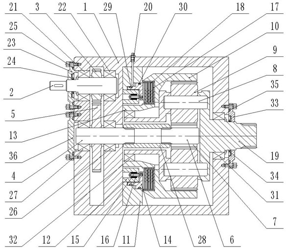
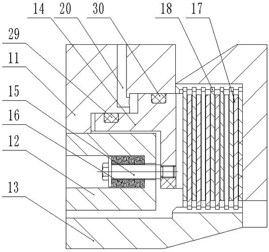
[0035]This embodiment provides a torque-limiting speed reducer for the transmission system of the mine conveying part, including a box body 1, an input gear shaft 2, an input gear 3, an intermediate gear shaft 4, an intermediate gear 5, a sun gear shaft 6, a sun gear 7, a planet Wheel shaft 8, planetary gear 9, floating ring gear 10, first support seat 11, second support seat 12, third support seat 13, piston 14, screw rod 15, disc spring group 16, static friction plate 17, dynamic friction plate 18, output Shaft 19 and planet carrier; input gear shaft 2 rotates and is installed on the box body 1, the input end is located outside the box body 1 for connection with the motor 201, input gear shaft 2 is fixedly sleeved with input gear 3; intermediate gear shaft 4 rotates Penetrated in the box 1, the intermediate gear shaft 4 is fixedly set with an intermediate gear 5, which meshes with the input gear 3, and the intermediate gear 5 is used to reduce the input speed of the input gea...

Embodiment 2

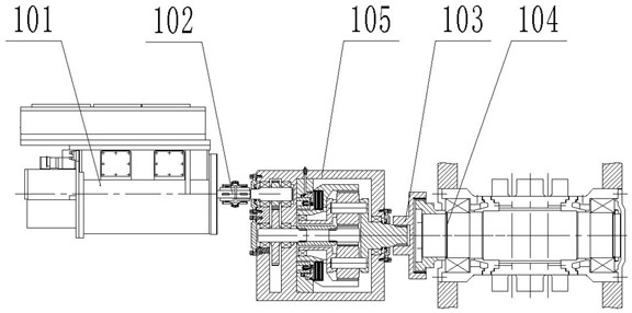
[0043] This embodiment provides a transmission system for mine conveying parts, including a motor 101, a shaft coupling 102, a transition plate 103, a sprocket 104, and the torque-limiting reducer 105 described in Embodiment 1; the motor 201 communicates with the The input gear shaft 2 of the torque limiting reducer 105 is connected; the sprocket 104 is connected with the output shaft 19 of the torque limiting reducer 105 through the transition plate 103 .

[0044] Further, the transmission system of the mine conveying part also includes a hydraulic control circuit, and the hydraulic control circuit includes a gear pump 106, a first overflow valve 107, a filter 108, a pressure gauge 109, a second overflow valve 110, and a solenoid valve 111 , throttle valve 112 and oil tank 113; the oil inlet of gear pump 106 is connected with oil tank 113, and oil outlet is connected with the first overflow valve 107 and filter 108 respectively; The first overflow valve 107 is connected back t...

Embodiment 3

[0050] This embodiment provides a control method for the transmission system of the mine conveying part, including a starting method:

[0051] S1, the motor 101 and the gear pump 106 start at the same time. When the oil does not enter the high-pressure oil passage 20, the dynamic friction plate 18 and the static friction plate 17 are separated, and the motor 101 outputs power to the input gear shaft 2. After reducing the speed through the intermediate gear 5, the The power is transmitted to the sun gear 7, the sun gear 7 drives the rotation of the planetary gear 9, the rotation of the sun gear 7 transmits the power to the planetary gear 9, the rotation of the planetary gear 9 drives the floating ring gear 10 to rotate, the dynamic friction plate 18 rotates, and the static friction plate 17 is fixed;

[0052] S2, the oil enters the high-pressure oil passage 20, overcomes the force of the disc spring group 16, and makes the piston 14 exert pressure on the dynamic friction plate 1...


PUM


Abstract

The invention provides a transmission system of a mine conveying part, its torque-limiting reducer and a control method, which belong to the technical field of coal mine underground equipment. Reducer; torque limiting reducer includes box, input gear shaft, input gear, intermediate gear shaft, intermediate gear, sun gear shaft, sun gear, planetary gear shaft, planetary gear, floating ring gear, first support seat, second support seat , The third support seat, piston, screw, disc spring group, static friction plate, dynamic friction plate, output shaft and planet carrier. The transmission system of the mining conveying part and its torque-limiting reducer and control method can well avoid the influence of the heavy-load start-up of the conveying part and the impact load of overload protection on the transmission system, improve the reliability and working efficiency of the equipment, and is relatively simple The advanced control system is convenient for the staff to operate and maintain, and reduces the vicious incidents caused by improper operation.

Description

technical field [0001] The invention belongs to the technical field of coal mine underground equipment, and specifically discloses a transmission system of a mine conveying part, a torque-limiting reducer and a control method thereof. Background technique [0002] The transportation part is an important transportation equipment in the fully mechanized mining face of the coal mine. It is responsible for the important tasks of transporting coal, providing the running track for the shearer, and providing the fulcrum for the hydraulic support. It has long distance, large capacity, high power, and long life. Features, the laying length is generally greater than 250m, or even more than 400m, and it is often necessary to install 2-4 transmission devices with a transmission efficiency of 700kW. The transmission system of the transmission part is mainly composed of drive motors, reducers and other components. , and it is also necessary to ensure the safety of the system when it is un...

Claims


Application Information

Patent Timeline
Patent Type & Authority Patents(China)
IPC IPC(8): F16D43/21F16D48/02F16D25/12F16H1/32
CPCF16D43/216F16D48/02F16D25/123F16D25/14F16H1/32F16H2001/327
Inventor 周开平王步康王学成张学荣马昭石涛郝建生王帅李刚桑盛远王传武秦国强张春英郎艳张洮张明秀
Owner TAIYUAN INST OF CHINA COAL TECH & ENG GROUP
Why Eureka
Try Eureka