Range hood

A technology for range hoods and hoods, which is applied to the removal of oil fume, household stoves/stoves, heating methods, etc., can solve problems such as uneven airflow and inability to suck up oil fume, so as to widen smoking channels, reduce air intake resistance, reduce The effect of changing the direction of the airflow

Active Publication Date: 2020-10-09
FOSHAN SHUNDE MIDEA WASHING APPLIANCES MFG CO LTD
View PDF10 Cites 0 Cited by
  • Summary
  • Abstract
  • Description
  • Claims
  • Application Information

AI Technical Summary

Problems solved by technology

However, when the cooking fume is generated on one side of the stove, most of the fume enters the range hood through only one side channel. Due to the uneven air flow, the one side channel cannot quickly suck the oil fume away.

Method used


Image

  • Range hood
  • Range hood
  • Range hood

Examples


Embodiment 1

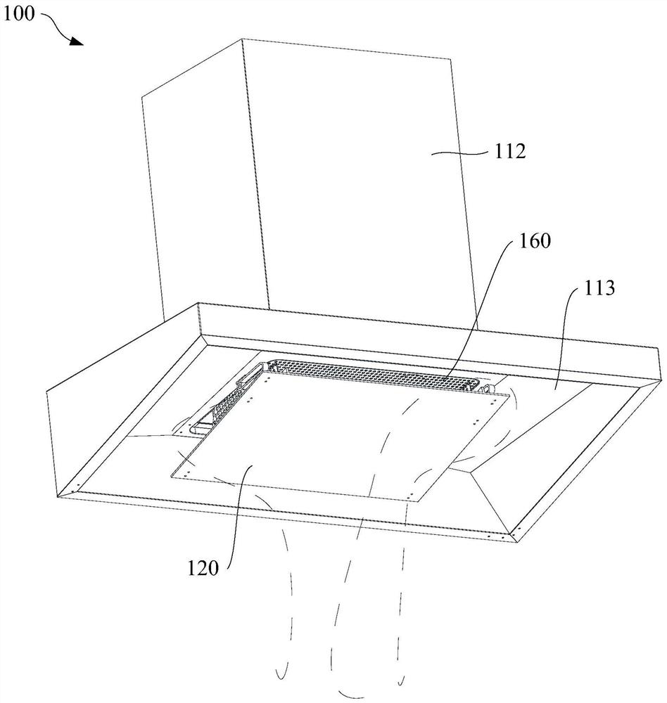
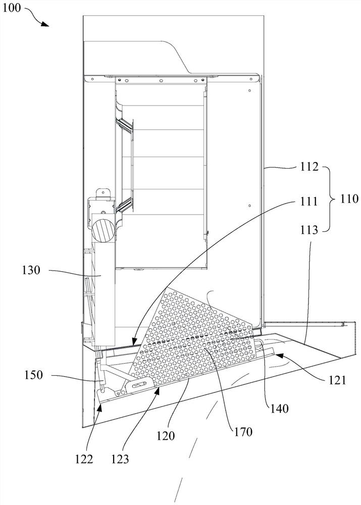
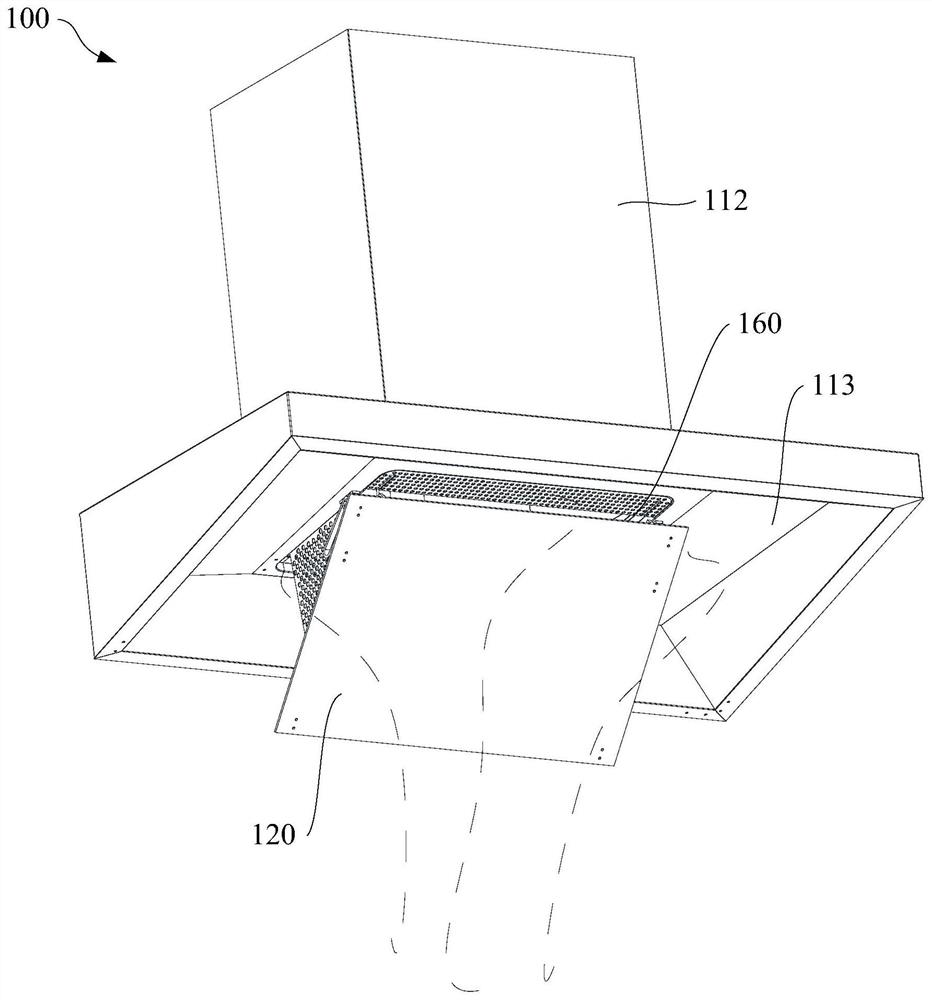
[0046] Such as Figure 1 to Figure 4 As shown (the dotted line in the figure shows the airflow direction), Embodiment 1 of the present invention provides a range hood 100 , and the range hood 100 includes a range hood body 110 , a condensation plate 120 , a drive assembly 130 and a limit assembly 140 . Wherein, the hood body 110 includes an air inlet 111; the condensing plate 120 is located at the air inlet 111, and the condensing plate 120 includes a first end 121 and a second end 122 facing away from each other; the driving assembly 130 is connected with the hood body 110, and the driving assembly 130 can drive the second end 122 of the condensation plate 120 to rotate around the first end 121 of the condensation plate 120; the limit assembly 140 connects the hood body 110 and the first end 121 of the condensation plate 120, and the limit assembly 140 can When the second end 122 of the plate 120 moves away from the air inlet 111 , the first end 121 of the condensation plate ...

Embodiment 2

[0050] On the basis of Embodiment 1, Embodiment 2 provides a range hood 100, wherein the drive assembly 130 is connected to the condensation plate 120, and the reliable connection between the drive assembly 130 and the condensation plate 120 can be realized, so that the drive assembly 130 not only The condensing plate 120 can be pushed to rotate away from the air inlet 111 , and the condensing plate 120 can also be pulled to rotate in a direction close to the air inlet 111 , so as to realize switching between different smoking states. In addition, the connection mode between the driving assembly 130 and the condensation plate 120 is specifically a rotational connection, which can realize the flexible rotation of the condensation plate 120 .

[0051] Specifically, such as Figure 6 and Figure 10 As shown, the driving assembly 130 includes a driving push rod 131 and a bending connecting arm 132. The driving pushing rod 131 is connected with the cigarette machine body 110, and ...

Embodiment 3

[0054] On the basis of any of the above embodiments, Embodiment 3 provides a range hood 100, wherein, as Figure 8 and Figure 9 As shown, the limiting assembly 140 includes a limiting groove 141 and a limiting protrusion 144 located therein, wherein one of the limiting groove 141 and the limiting protrusion 144 is connected to the smoke machine body 110, and the limiting groove 141 and the limiting protrusion 144 The other of the limiting protrusions 144 is connected to the first end 121 of the condensing plate 120, for example, the limiting groove 141 is connected to the hood body 110, and the limiting protrusion 144 is connected to the first end 121 of the condensing plate 120. connect. The limiting protrusion 144 extends along the depth direction of the limiting groove 141 , the limiting protrusion 144 can rotate in the limiting groove 141 , and the limiting protrusion 144 can reciprocate along the length direction of the limiting groove 141 . By making the limiting prot...


PUM


Abstract

The embodiment of the invention provides a range hood. The range hood comprises a range hood body, a condensation plate, a driving assembly and a limiting assembly, wherein the range hood body comprises an air inlet, the condensation plate is located at the air inlet and comprises a first end and a second end which away from each other, the driving assembly is connected with the range hood body, the driving assembly can drive the second end of the condensation plate to rotate around the first end of the condensation plate, the range hood body is connected with the first end of the condensationplate through the limiting assembly, and the limiting assembly can guide the first end of the condensation plate to move towards the center line of the air inlet in a process that the second end of the condensation plate moves in the direction away from the air inlet. By arranging the driving assembly and the limiting assembly, the size of a lampblack channel between the condensation plate and the air inlet can be changed according to needs under the condition of lower mechanism cost, the lampblack suction capacity of the range hood is adjusted, lampblack or airflow can enter the interior ofthe range hood more quickly, the lampblack overflowing is prevented, and the lampblack suction requirement of a user is met.

Description

technical field [0001] Embodiments of the present invention relate to the technical field of kitchen equipment, in particular, to a range hood. Background technique [0002] Conventional European-style range hoods are equipped with a condensation plate under the air inlet to block the oil and water dripping from the inside of the range hood. At the same time, the setting of the condensing plate can expand the negative pressure area at the bottom of the hood, enhance the smoking capacity around the hood, and prevent the oil fume from overflowing. In addition, during the cooking process, the oily fume touches the condensing plate first, and the oily fume is more likely to be intercepted by the filter after being condensed by the condensing plate. In the related art, in order to improve the smoking effect of conventional European-style hoods, the condensation plate and the left and right front sides of the hood deflector often form channels with a fixed width for air flow. In...

Claims


Application Information

Patent Timeline
Patent Type & Authority Applications(China)
IPC IPC(8): F24C15/20
CPCF24C15/2035
Inventor 谭柏豪马世涛孙培原蒋济武
Owner FOSHAN SHUNDE MIDEA WASHING APPLIANCES MFG CO LTD
Why Eureka
Try Eureka