Robot path planning method based on multiple regions, robot and terminal equipment

A path planning and robotics technology, applied in the field of robotics, to achieve the effect of improving efficiency and ensuring accuracy

Inactive Publication Date: 2020-10-09
深圳优地科技有限公司
View PDF11 Cites 17 Cited by
  • Summary
  • Abstract
  • Description
  • Claims
  • Application Information

AI Technical Summary

Problems solved by technology

[0004] In view of this, the embodiment of the present application provides a multi-region-based robot path planning method, a robot and a terminal device to solve the problem of how to accurately and efficiently implement multi-region-based robot path planning in the prior art

Method used


Image

  • Robot path planning method based on multiple regions, robot and terminal equipment
  • Robot path planning method based on multiple regions, robot and terminal equipment
  • Robot path planning method based on multiple regions, robot and terminal equipment

Examples


Embodiment 1

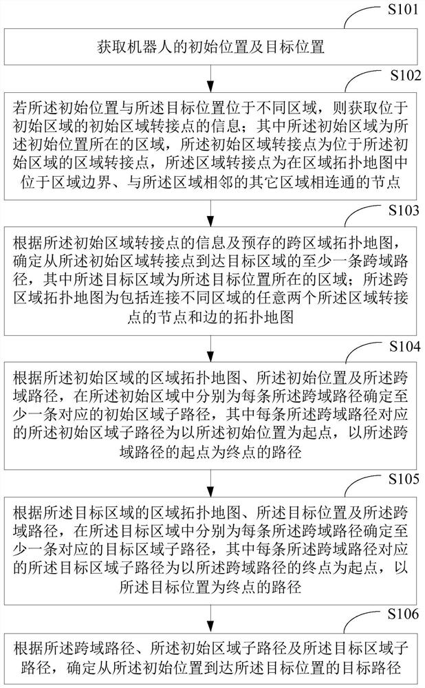
[0037] figure 1 It shows a schematic flow chart of a multi-region-based robot path planning method provided by the embodiment of the present application. The execution subject of the multi-region-based robot path planning method is a robot. The details are as follows:

[0038] In S101, an initial position and a target position of the robot are acquired.

[0039] When the robot receives the moving task, the position of the robot at this time is obtained as the initial position, and the final position to be reached by the moving task is obtained as the target position.

[0040] Optionally, before acquiring the initial position and the target position of the robot, the robot acquires a mobile task dispatch instruction carrying information about the target position, and the mobile task dispatch instruction may be sent to the robot by other terminal equipment (such as a server or a user terminal). The robot can also be generated by the user directly operating on the robot's operat...

Embodiment 3

[0118] Figure 5 It shows a schematic structural diagram of a robot provided by the embodiment of the present application. For the convenience of description, only the parts related to the embodiment of the present application are shown:

[0119] The robot includes: a location acquisition unit 51 , an initial area transfer point acquisition unit 52 , a cross-domain route determination unit 53 , an initial area sub-route determination unit 54 , and a target area sub-route determination unit 55 . in:

[0120] The position obtaining unit 51 is used to obtain the initial position and the target position of the robot.

[0121] An initial area transfer point acquisition unit 52, configured to acquire information on an initial area transfer point located in the initial area if the initial position and the target position are located in different areas; wherein the initial area is where the initial position is located area, the initial area transition point is an area transition poi...

Embodiment 4

[0138] Figure 6 It is a schematic diagram of a terminal device provided by an embodiment of the present application. Such as Figure 6 As shown, the terminal device 6 of this embodiment includes: a processor 60, a memory 61, and a computer program 62 stored in the memory 61 and operable on the processor 60, such as a multi-region-based robot path planning program . When the processor 60 executes the computer program 62, it realizes the steps in the above embodiments of the multi-region-based robot path planning method, for example figure 1 Steps S101 to S106 are shown. Alternatively, when the processor 60 executes the computer program 62, it realizes the functions of the modules / units in the above-mentioned device embodiments, for example Figure 5 Function of units 51 to 56 shown.

[0139]Exemplarily, the computer program 62 can be divided into one or more modules / units, and the one or more modules / units are stored in the memory 61 and executed by the processor 60 to co...


PUM


Abstract

The invention is suitable for the technical field of robots, and provides a robot path planning method based on multiple regions, a robot and terminal equipment, and the method comprises the steps: obtaining an initial position and a target position of the robot; if the initial position and the target position are located in different areas, obtaining information of a switching point located in the initial area; determining cross-domain paths according to the information of the switching point in the initial area and a pre-stored cross-domain topological map; determining a corresponding initial area sub-path for each cross-domain path according to the area topological map, the initial position and the cross-domain path of the initial area; determining a corresponding target area sub-path for each cross-domain path according to the area topological map of the target area, the target position and the cross-domain path; and determining a target path according to the cross-domain path, theinitial area sub-path and the target area sub-path. According to the embodiment of the invention, robot path planning based on multiple regions can be efficiently realized.

Description

technical field [0001] The present application belongs to the field of robot technology, and in particular relates to a multi-area-based robot path planning method, robot and terminal equipment. Background technique [0002] With the development of robot technology, robots with autonomous navigation function (ie, mobile robots capable of autonomous path planning) are widely used in various scenarios. These scenes include indoor scenes inside buildings such as office buildings and residential houses, as well as lawns, sports fields, passages between buildings, etc., and outdoor scenes located outside the building. Due to the different characteristics of the actual environment of different scenes, in the prior art, a separate area map is usually set for each scene, and a single robot is only limited to work in the area of ​​a single scene, and the robot path is planned according to the area map of the scene , realize robot autonomous navigation. [0003] However, with the im...

Claims


Application Information

Patent Timeline
Patent Type & Authority Applications(China)
IPC IPC(8): G01C21/20
CPCG01C21/206G01C21/20
Inventor 夏舸赖馨钻刘文泽李超
Owner 深圳优地科技有限公司
Why Eureka
Try Eureka