Floating ball liquid level meter capable of improving flexibility of floating ball

A floating ball liquid level, flexible technology, applied in the direction of buoy liquid level indicator, liquid level indicator, liquid/fluid solid measurement, etc., can solve the problems of inaccurate liquid level detection, error, shaking, etc. ball shaking effect

Active Publication Date: 2020-10-09
QIDONG NANHUA INSTR EQUIP
View PDF4 Cites 3 Cited by
  • Summary
  • Abstract
  • Description
  • Claims
  • Application Information

AI Technical Summary

Problems solved by technology

[0003] But the existing ball float level gauge also has the following problems in the actual use process: first, due to the movable socket between the float ball and the guide rod, the ball float level gauge will follow the liquid level during actual use. When the distance between the inner wall of the float and the guide rod is small, the friction between the inner wall of the float and the guide rod is serious, which increases the friction resistance of the float. When the distance between the inner wall of the float and the guide rod is large, The floating ball may shake on the liquid surface, which will lead to inaccurate liquid level detection; secondly, in actual use, most of the floating ball level gauges work in harsh environments, such as the detection of liquids such as oil, resulting in the liquid level of the floating ball There will be a lot of dirt on the connecting pipe of the potentiometer, which can block the floating ball, causing the floating ball to not slide well, so that the measured data will be inaccurate or have a large error

Method used


Image

  • Floating ball liquid level meter capable of improving flexibility of floating ball
  • Floating ball liquid level meter capable of improving flexibility of floating ball
  • Floating ball liquid level meter capable of improving flexibility of floating ball

Examples


Embodiment Construction

[0020] The following will clearly and completely describe the technical solutions in the embodiments of the present invention with reference to the accompanying drawings in the embodiments of the present invention. Obviously, the described embodiments are only some, not all, embodiments of the present invention. Based on the embodiments of the present invention, all other embodiments obtained by persons of ordinary skill in the art without making creative efforts belong to the protection scope of the present invention.

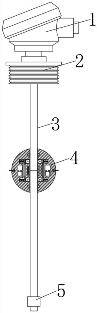
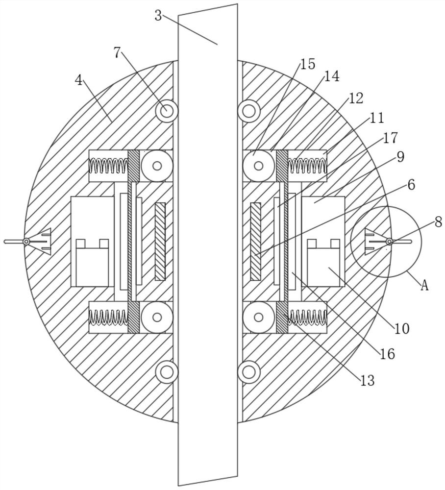
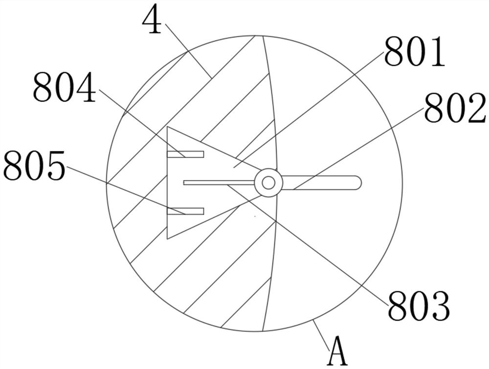
[0021] see Figure 1-6 , a kind of floating ball liquid level gauge that improves the flexibility of the floating ball, comprising a display device 1, the bottom of the display device 1 is fixedly connected with a threaded connector 2, the middle part of the bottom end of the threaded connector 2 is fixedly connected with a guide rod 3, and the guide rod 3 The outer side of the floating ball is movable socketed with a floating ball 4, the bottom of the guide r...


PUM


Abstract

The invention relates to the technical field of instruments and meters. The invention further discloses a floating ball liquid level meter capable of improving the flexibility of a floating ball. Thefloating ball liquid level meter comprises a display device, the bottom of the display device is fixedly connected with a threaded connecting piece, a guide rod is fixedly connected to the middle of the bottom end of the threaded connecting piece, a floating ball is movably connected to the outer side of the guide rod in a sleeving mode, a lower baffle is fixedly connected to the bottom of the guide rod, a magnetic ring is arranged in the floating ball, and the bottom and the top of an inner ring of the floating ball are each movably provided with a set of balls. Through arrangement of a detection device and a driving wheel, when the floating ball liquid level meter works normally, the driving wheel is far away from the guide rod, and the normal work of the floating ball is not influenced;when the floating ball is stuck by dirt and cannot work normally, an electromagnet is powered on to generate magnetism, so that the driving wheel moves towards the guide rod, the driving wheel and the guide rod are in contact with each other, contact pressure is generated, the driving wheel rotates at the moment, the floating ball can be driven to move upwards or downwards, and therefore the height of the liquid level is accurately measured.

Description

technical field [0001] The invention relates to the technical field of instruments and meters, in particular to a float level gauge which improves the flexibility of the float. Background technique [0002] The structure of the float level gauge is mainly designed and produced based on the principle of buoyancy and static magnetic field. The magnet and the sensor (reed switch function) change the number of components connected in series to the circuit (such as fixed-value resistors, which in turn changes the electrical quantity of the instrument circuit system, that is, changes in the position of the magnetic float cause changes in the electrical quantity It is an instrument that reflects the liquid level in the container by detecting the change of electrical quantity. This instrument is suitable for sewage treatment in industries such as petroleum, chemical industry, electric power, light industry and medicine, and for measuring the liquid level of media in various normal p...

Claims


Application Information

Patent Timeline
Patent Type & Authority Applications(China)
IPC IPC(8): G01F23/68G01F23/72G01F23/76
CPCG01F23/683G01F23/72G01F23/76
Inventor 陈雪
Owner QIDONG NANHUA INSTR EQUIP
Why Eureka
Try Eureka