
Backlight module and display device

A technology of backlight module and light source, applied in the direction of light guide, optics, optical components, etc., can solve the problems of light leakage, affecting the optical effect of the backlight module, light leakage of the light source, etc., and achieve the effect of reducing the width of the black border

Pending Publication Date: 2020-10-09
RADIANT OPTO ELECTRONICS SUZHOU
View PDF0 Cites 0 Cited by
  • Summary
  • Abstract
  • Description
  • Claims
  • Application Information

AI Technical Summary

Problems solved by technology

As a result, the light from the light source leaks out, which seriously affects the optical effect of the backlight module
In addition, this design needs to lock multiple screws, and the screws will pass through the back panel of the backlight module, causing the light when the backlight module emits light to easily leak from the locking part of the back panel

Method used


Image

  • Backlight module and display device
  • Backlight module and display device
  • Backlight module and display device

Examples


Embodiment Construction

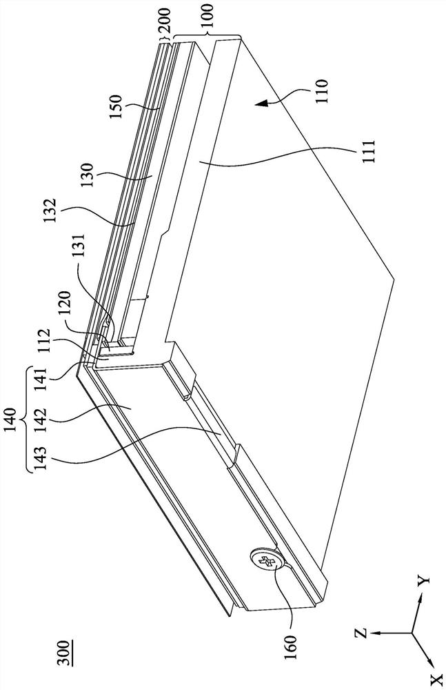
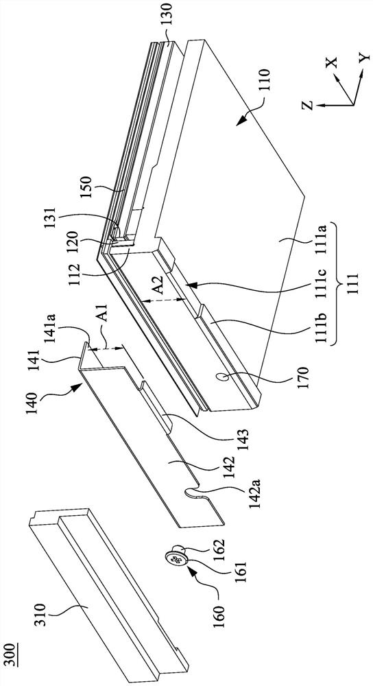
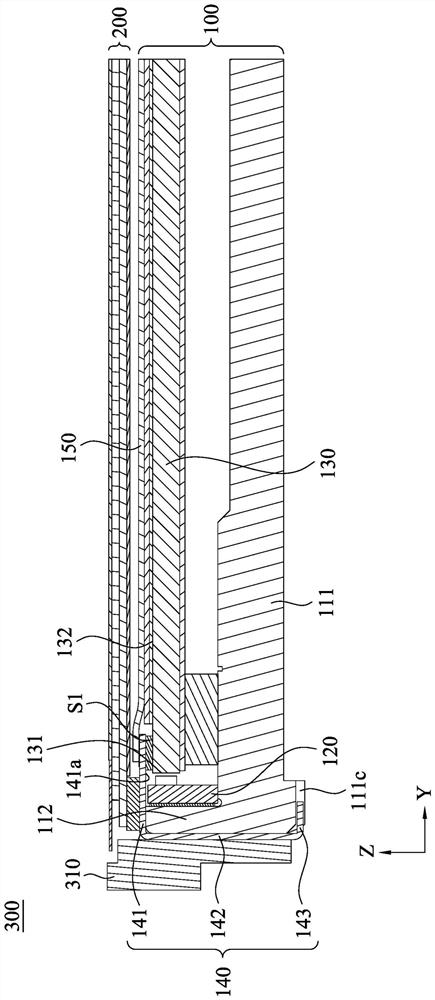
[0025] Also refer to figure 1 and figure 2 , which respectively show a device schematic diagram and an exploded schematic diagram of a display device according to an embodiment of the present invention. The display device 300 of this embodiment includes a backlight module 100 and a display panel 200 disposed in front of the backlight module 100 . The backlight module 100 mainly includes a carrier 110 , a light source 120 , a light guide plate 130 , a pressing unit 140 and a plurality of optical films 150 .

[0026] Such as figure 1 and figure 2 As shown, the carrier 110 includes a carrier portion 111 and a side wall 112. The carrying portion 111 extends along a horizontal direction (such as the Y direction shown in the figure), and the side wall 112 is disposed on one side of the carrying portion 111 and extends along a vertical direction (such as the Z direction shown in the figure). In one example, the carrying portion 111 and the side wall 112 jointly form an L-shape...


PUM


Abstract

The invention provides a backlight module and a display device. The backlight module comprises a bearing piece, a light source, a light guide plate and a pressing unit. The bearing piece comprises a bearing part and a side wall arranged on the side edge of the bearing part. The light source is arranged on the bearing part. The light guide plate is arranged on the bearing part. The light incident surface of the light guide plate is adjacent to the light source. The pressing unit comprises a flat plate part, a side plate part and a bottom plate part. The flat plate part extends in the horizontaldirection and covers the light source. The flat plate part is provided with a pressing surface abutting against the top surface of the side wall and an optical surface of the light guide plate. The side plate part is connected with the flat plate part and extends in the vertical direction. The bottom plate part is connected with the side plate parts, extends in the horizontal direction and abutsagainst the bottom face of the bearing part.

Description

technical field [0001] The invention relates to a light source module, in particular to a backlight module and its application on a display device. Background technique [0002] The display device mainly includes a backlight module, a plastic frame and a display panel, and the display panel is mainly carried on the backlight module through the plastic frame. Wherein, the backlight module mainly includes a backplane, a light guide plate, an optical film and a light source arranged in the backplane. [0003] After a general backlight module is used for a period of time, the light guide plate and the part of the plastic frame close to the light source will be deformed or warped due to heat, and then the plastic frame will be stretched apart. As a result, the light from the light source leaks out, which seriously affects the optical effect of the backlight module. In addition, this design needs to lock multiple screws, and the screws will pass through the back panel of the bac...

Claims


Application Information

Patent Timeline
IPC IPC(8): G09F9/00G02B6/00
CPCG02B6/0088G09F9/00
Inventor 黄镫仪赵永杰陈致尧
Owner RADIANT OPTO ELECTRONICS SUZHOU
Learn More