Multi-frequency antenna architecture

A multi-frequency antenna and antenna technology, applied in the direction of antenna, antenna coupling, loop antenna, etc., can solve the problems of mutual interference of antenna signals, lack of overall consideration, and inability to solve the problem of antenna unit isolation

Active Publication Date: 2020-10-09
ELECTRIC CONNECTOR TECH +1
View PDF4 Cites 1 Cited by
  • Summary
  • Abstract
  • Description
  • Claims
  • Application Information

AI Technical Summary

Problems solved by technology

At present, most antenna designs place multi-unit sub-6GHz MIMO antennas on the side of wireless communication devices (such as 5G mobile phones, etc.), and some designs also choose to place 5G millimeter wave antennas on the side. These designs are It was proposed for its own single design, lacking overall consideration, and did not consider the rationality of the layout when multiple different frequency band antennas coexist from the overall layout, and did not take into account the three types of LTE m

Method used


Image

  • Multi-frequency antenna architecture

Examples


Embodiment Construction

[0022] In order to make the purpose, technical solution and advantages of the present application clearer, the present application will be further described in detail below in conjunction with the accompanying drawings and embodiments. It should be understood that the specific embodiments described here are only used to explain the present application, and are not intended to limit the present application. The wireless communication device can be a mobile phone, a tablet computer, a notebook, a dual-screen tablet computer, and other electronic equipment with communication functions. It should be noted that the terms "outer left", "outer right", "inner left", "inner right", "middle region" and the "upper portion" and "lower end portion" of each region are only intended to provide a relative reference to these orientations. The location is used for reference purposes and is not limited by location.

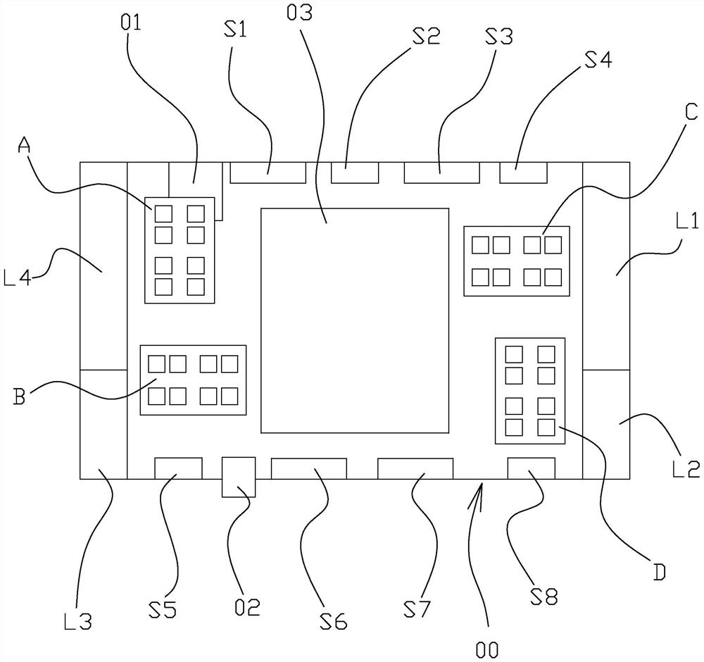
[0023] Please refer to figure 1 As shown, it shows a schematic structural dia...


PUM


Abstract

The invention relates to a multi-frequency antenna architecture. The antenna architecture is arranged in a base body of the wireless communication device, and the antenna architecture comprises firstantennas which are typically LTE and are located in the left outer side area and the right outer side area in the base body; second antennas which are positioned in the upper outer side area and the lower outer side area in the base body and are typically Sub-6GHz MIMO; third antennas which are positioned in the left inner side area and the right inner side area in the base body and are typicallymillimeter waves, wherein the areas are arranged at intervals, the first, second and third antennas work in different frequency bands, and the third antennas can realize broadband large-angle beam scanning, thereby effectively expanding the radiation performance of the millimeter wave antenna, and improving and solving the mutual interference among antenna signals in different frequency bands in alimited space. The technical scheme disclosed by the invention is easy to integrate, excellent in radiation and good in isolation.

Description

technical field [0001] The invention relates to the technical field of antennas, in particular to an antenna structure applied to multi-frequency wireless communication of a mobile communication device. Background technique [0002] With the advent of the 5G era, the antennas of wireless communication devices tend to develop from single-frequency antennas to multi-frequency antennas, and it is often necessary to design and layout antennas of various frequency bands in a limited space. For example, 5G (fifth generation mobile Communication technology) mobile phone terminals often need to design and layout sub-6GHz in a limited space [0003] Antennas of different frequency bands such as MIMO, LTE, WIFI, GPS, millimeter wave, etc. can realize various functions. At present, most antenna designs place multi-unit sub-6GHz MIMO antennas on the side of wireless communication devices (such as 5G mobile phones, etc.), and some designs also choose to place 5G millimeter wave antennas...

Claims


Application Information

Patent Timeline
IPC IPC(8): H01Q21/30H01Q1/52H01Q5/10H01Q5/20H01Q5/307H01Q1/24H01Q1/22
CPCH01Q21/30H01Q1/521H01Q5/10H01Q5/20H01Q5/307H01Q1/242H01Q1/2258H01Q1/243H01Q7/00H01Q21/28H01Q5/40H01Q5/30
Inventor 杨广立王明凯徐加友罗勇李祎昕罗云张涛张英杰任宇骏
Owner ELECTRIC CONNECTOR TECH
Why Eureka
Try Eureka