
Smart watch and combination of smart watch and charging base

A smart watch and charging stand technology, which is applied in the field of smart wearables, can solve the problems of occupying the space of smart watches, unfavorable real-time monitoring of the user's body, and unfavorable integrated design of smart watches, etc., to achieve the effect of improving the appearance

Pending Publication Date: 2020-10-09
XIAN YIPU COMM TECH
View PDF8 Cites 2 Cited by
  • Summary
  • Abstract
  • Description
  • Claims
  • Application Information

AI Technical Summary

Problems solved by technology

[0002] At present, the charging design of smart watches is either to set the charging structure at the bottom of the watch body, or to set the charging structure on the side of the watch body. No matter which solution is used, it will occupy the use space of the smart watch, which is obviously not conducive to the smart watch. integrated design
Moreover, when the charging structure is arranged on the side of the watch body, it is easy to affect the appearance of the smart watch
In addition, when the current smart watch needs to be charged, the smart watch must be removed from the user to charge, which is obviously not conducive to real-time monitoring of the user's body.

Method used


Image

  • Smart watch and combination of smart watch and charging base
  • Smart watch and combination of smart watch and charging base
  • Smart watch and combination of smart watch and charging base

Examples


Embodiment Construction

[0022] In order to describe the technical content and structural features of the present invention in detail, further description will be given below in conjunction with the implementation and accompanying drawings.

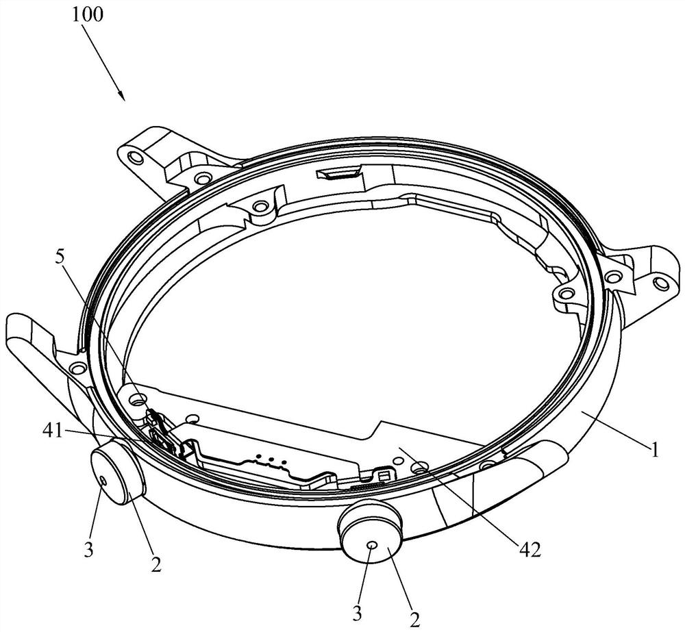
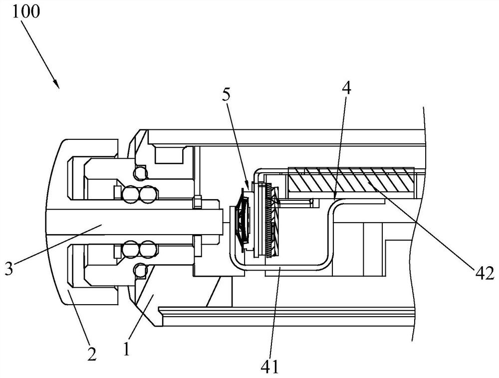
[0023] see figure 1 , figure 2 and Figure 6 , the present invention discloses a smart watch 100, comprising a housing 1, at least two plastic key caps 2, two charging terminals 3, an internal charging module 4, a key function module 5 and a processing module 6, and the two plastic key caps 2 are installed at intervals On the side wall of the housing 1, two charging terminals 3 are respectively injection-molded in the two plastic key caps 2, one end of the charging terminal 3 is exposed on the outside of the plastic key cap 2, and the other end of the charging terminal 3 is exposed on the inside of the plastic key cap 2 ; Under normal conditions, the two charging terminals 3 are separated from the internal charging module 4; when the plastic key cap 2 is in th...


PUM


Abstract

The invention discloses a smart watch and a combination of the smart watch and a charging base. The smart watch comprises a shell body, at least two plastic key caps, two charging terminals, an internal charging module, a key function module and a processing module, wherein the two plastic key caps are installed on the side wall of the shell body in a spaced mode, the two charging terminals are formed in the two plastic key caps in an injection molding mode respectively, one end of each charging terminal is exposed to the outer side of the corresponding plastic key cap, and the other end of each charging terminal is exposed to the inner side of the corresponding plastic key cap. In a normal state, the two charging terminals are separated from the internal charging module. When the plastickey caps are in a pressed state, the two charging terminals are connected with the internal charging module; the key function module can perform state switching according to the pressing of the plastic key cap, and the processing module can perform a corresponding control function according to the state switching information of the key function module. According to the smart watch and the combination of the smart watch and the charging base, the integrated design of the smart watch is facilitated, and the appearance of the smart watch can be improved.

Description

technical field [0001] The invention relates to the technical field of smart wear, in particular to a smart watch and its combination with a charging stand. Background technique [0002] At present, the charging design of smart watches is either to set the charging structure at the bottom of the watch body, or to set the charging structure on the side of the watch body. No matter which solution is used, it will occupy the use space of the smart watch, which is obviously not conducive to the smart watch. Integrated design. Moreover, when the charging structure is arranged on the side of the watch body, it is easy to affect the appearance of the smart watch. In addition, when the current smart watch needs to be charged, the smart watch must be removed from the user to be charged, which is obviously not conducive to real-time monitoring of the user's body. Contents of the invention [0003] The purpose of the present invention is to provide a smart watch, which is beneficia...

Claims


Application Information

Patent Timeline
Patent Type & Authority Applications(China)
IPC IPC(8): H02J7/00G04G21/08G04G19/00G04G17/08G04G17/06
CPCH02J7/0042H02J7/0045G04G21/08G04G19/00G04G17/06G04G17/08
Inventor 王博王凯郑腾飞李学铭成卫卫
Owner XIAN YIPU COMM TECH
Learn More