Charge pump and active loop filter with shared unity gain buffer

A unit-gain buffer, charge pump technology, applied in electrical components, automatic power control, conversion equipment without intermediate conversion to AC, etc., can solve problems such as increased cost, high power, and large die area.

Pending Publication Date: 2020-10-09
SILICON LAB INC
View PDF0 Cites 0 Cited by
  • Summary
  • Abstract
  • Description
  • Claims
  • Application Information

AI Technical Summary

Problems solved by technology

Typically, these PLLs are not optimized for delta-sigma ADCs, therefore, these PLLs consume high power and occupy a large die area, increasing cost

Method used


Image

  • Charge pump and active loop filter with shared unity gain buffer
  • Charge pump and active loop filter with shared unity gain buffer
  • Charge pump and active loop filter with shared unity gain buffer

Examples


Embodiment Construction

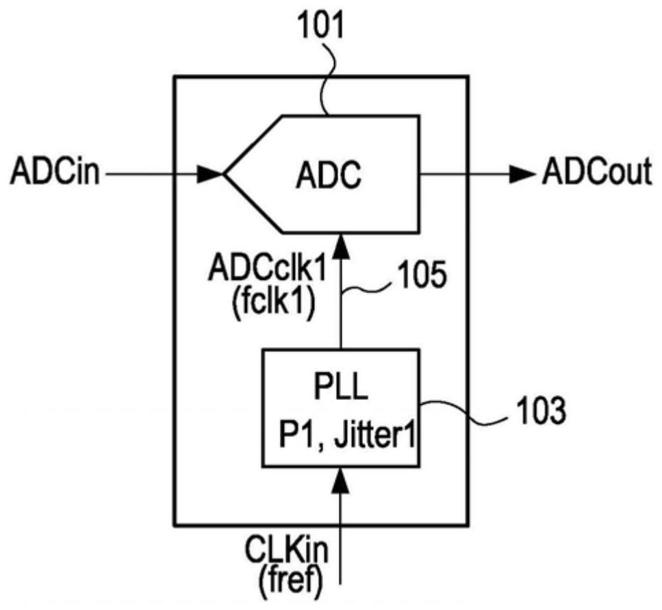
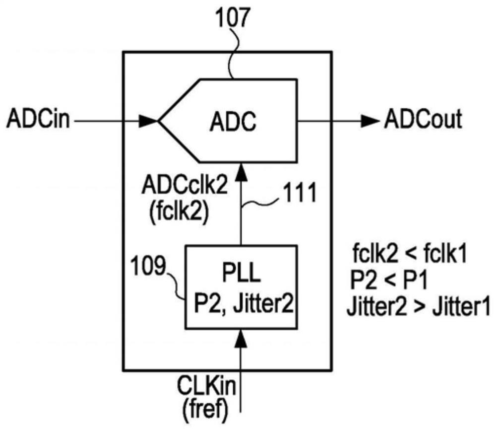
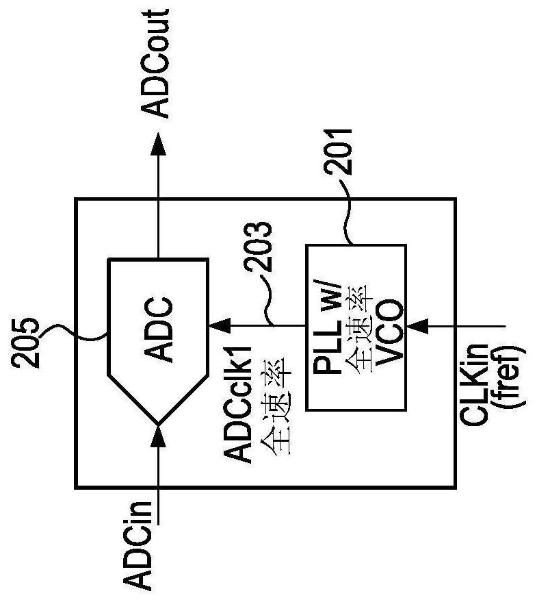
[0030] Embodiments described herein provide a phase-locked loop (PLL) specifically targeted for clock generation of a continuous time delta-sigma modulator ADC in a radio frequency receiver (RF RX) signal chain. For a given power budget, the PLL minimizes far-end phase noise at the expense of looser closure in phase noise. PLLs can also be used in other applications. Embodiments provide a variable power consumption PLL, wherein PLL power consumption is selected based on ADC requirements. For example, the PLL power can be scaled based on the input signal strength to the RX signal chain and / or based on the required clock rate of the ADC. Embodiments provide a fixed rate clock to the ADC, thereby avoiding the complexity of using a divided LO clock, thereby simplifying the design of the modem.

[0031] In one embodiment, for a 2MHz bandwidth, the ADC clock rate is approximately 307.2MHz. The integrated ADC noise bandwidth of 2MHz is mainly used for Zigbee applications. An ADC ...


PUM


Abstract

A unity gain buffer shared by a charge pump and an active loop filter in a phase-locked loop is disclosed. The charge pump uses the unity gain buffer to reduce current mismatch in the charge pump andthe active loop filter uses the unity gain buffer in a circuit that increases the effective capacitance of the active loop filter.

Description

technical field [0001] The present disclosure relates to generating clock signals, and more particularly, to generating clock signals in phased-locked loops (PLLs) with different power and jitter settings. Background technique [0002] Analog to digital converters (ADCs) based on continuous-time delta-sigma modulators (continuous-time delta-sigma modulators) are widely used in radiofrequency (RF) receiver (RX) applications middle. Typically, a high-order delta-sigma modulator-based ADC using a reference clock (eg, a crystal oscillator) or a less complex lower-order delta-sigma ADC with a higher clock rate is employed. For the second case, in one solution, the clock of the ADC is generated by a frequency-divided local oscillator (local oscillator, LO) clock. However, the LO clock signal may vary based on the tuning channel, causing the ADC sampling frequency to vary, complicating the modem design. Another method is to use a phase-locked loop (phased-locked loop, PLL) circu...

Claims


Application Information

Patent Timeline
Patent Type & Authority Applications(China)
IPC IPC(8): H03L7/089
CPCH03L7/0891H03L7/0802H03L7/0895H03L7/0896H03L7/093H02M3/07
Inventor 阿卜杜勒克里姆·L·科班
Owner SILICON LAB INC
Why Eureka
Try Eureka