
Metal pipe bending device with protection function

A technology of metal pipe fittings and bending devices, which is applied in the direction of feeding devices, positioning devices, storage devices, etc., can solve problems such as inconvenient operation, work-related injuries, and large deviations in bending accuracy, and achieve convenient installation and removal, and good protection , to avoid the effect of accidental touch

Inactive Publication Date: 2020-10-13
广州京海科技有限公司
View PDF0 Cites 6 Cited by
  • Summary
  • Abstract
  • Description
  • Claims
  • Application Information

AI Technical Summary

Problems solved by technology

[0003] In the process of use, in order to change the direction of the pipeline, it is often necessary to bend the pipe fittings. In some household occasions, it is generally directly bent manually through devices such as wire cutters, which is laborious and has a large deviation in bending accuracy. , and for manufacturers who mass-produce bent pipes, they generally use bending devices for bending
[0004] However, the existing bending device does not have better protection measures. The operation switch can be triggered by a simple button. When installing or removing the pipe fitting, once the operator touches the button by mistake, the device will run immediately, which may easily cause work-related injuries. The existing bending device needs to manually clamp and fix the pipe fittings, which is inconvenient to operate and affects work efficiency

Method used


Image

  • Metal pipe bending device with protection function
  • Metal pipe bending device with protection function
  • Metal pipe bending device with protection function

Examples


Embodiment Construction

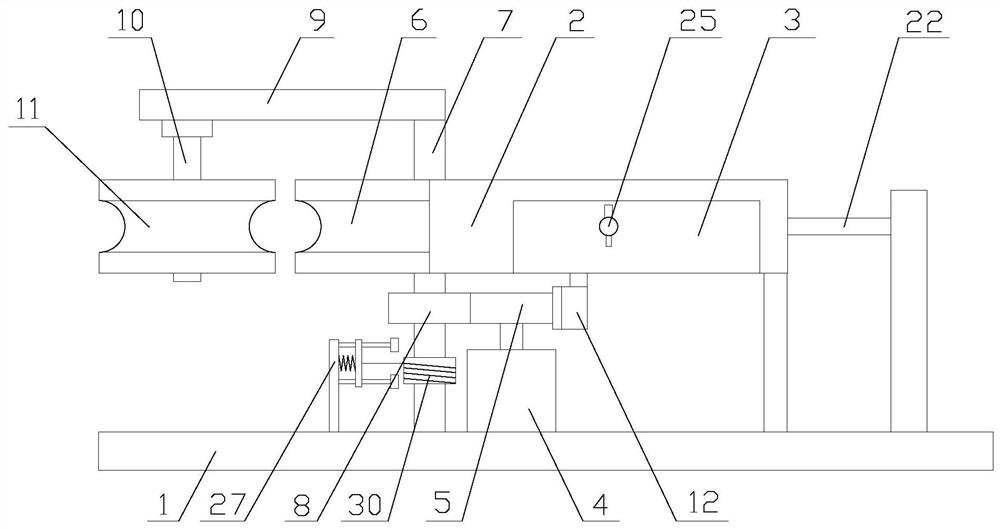
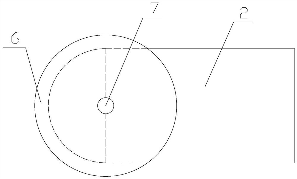
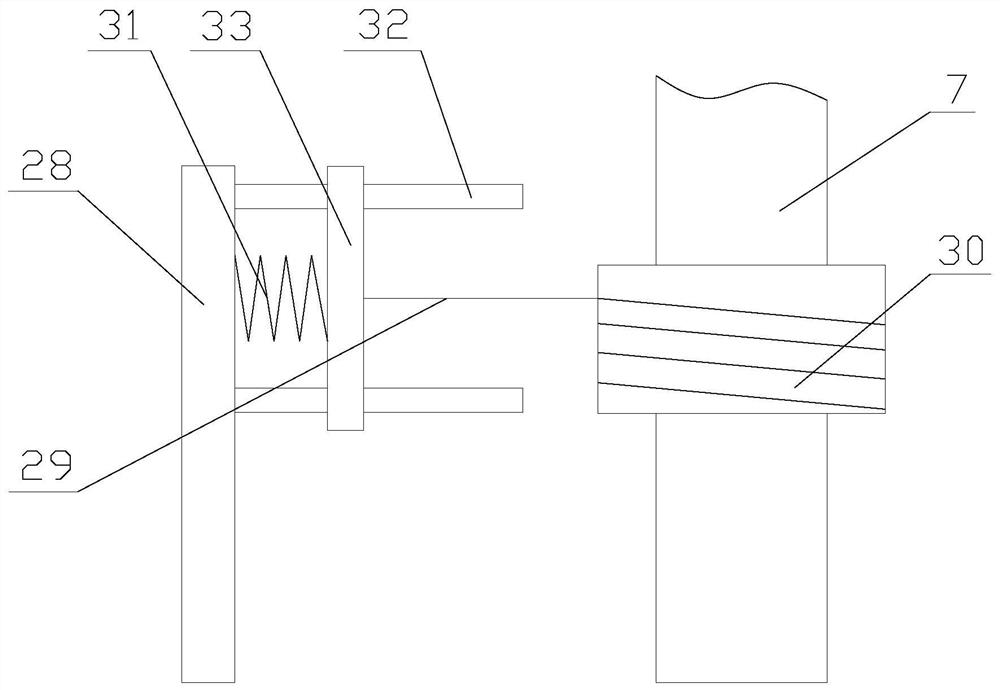
[0029] The present invention is described in further detail now in conjunction with accompanying drawing. These drawings are all simplified schematic diagrams, which only illustrate the basic structure of the present invention in a schematic manner, so they only show the configurations related to the present invention.

[0030] Such as figure 1 As shown, including a base 1, a fixed plate 2, a driving mechanism, a forming mechanism, a clamping mechanism and a control mechanism, the fixed plate 2 and the forming mechanism are all arranged on the base 1, and the clamping mechanism is arranged on the fixed plate 2 , the fixed plate 2 is provided with a notch, one end of the notch is provided with a baffle 3, and the control mechanism is arranged on the baffle 3;

[0031] The device drives the clamping mechanism to clamp the workpiece through the driving mechanism, and at the same time drives the forming mechanism to bend the pipe to realize the bending of the pipe, and realizes p...


PUM


Abstract

The invention relates to a metal pipe bending device with a protection function. The metal pipe bending device comprises a base, a fixing plate, a drive mechanism, a forming mechanism, a clamping mechanism and a control mechanism. According to the metal pipe bending device with the protection function, the drive assembly drives the forming mechanism to achieve bending forming of a pipe, the driveassembly drives two clamping blocks to be close to and away from each other, the workpiece is clamped and loosened, the device stops operating through the control mechanism, and operators are protected; compared with an existing bending device, according to the device, through linkage of the forming mechanism and the clamping mechanism, the pipe is more conveniently mounted and taken down; compared with an existing clamping mechanism, flexible clamping is adopted in the mechanism, and the situation that the workpiece is scratched by rigid clamping is avoided; and compared with an existing button control mechanism, a complex opening manner is adopted in the control mechanism, mis-touch is avoided, and the operators are better protected.

Description

technical field [0001] The invention relates to a metal pipe fitting bending device with protection function. Background technique [0002] Pipe fittings are a general term for parts that play the roles of connection, control, direction change, diversion, sealing, support, etc. in the pipeline system. Steel pipe fittings are all pressure-bearing pipe fittings. According to different processing techniques, they are divided into four categories, namely butt welding Fittings, socket welds, threaded fittings and flanged fittings. [0003] In the process of use, in order to change the direction of the pipeline, it is often necessary to bend the pipe fittings. In some household occasions, it is generally directly bent manually by means of wire cutters and other devices. The operation is laborious and the bending accuracy is relatively large. , and for manufacturers who mass-produce bent pipes, they generally use bending devices for bending. [0004] However, the existing bending...

Claims


Application Information

Patent Timeline
Patent Type & Authority Applications(China)
IPC IPC(8): B21D7/16B21D43/00B21D55/00
CPCB21D7/16B21D43/003B21D55/00
Inventor 曹燕红
Owner 广州京海科技有限公司
Learn More