Automatic uniform drilling device for birdcage top frame
What is AI technical title?
AI technical title is built by Patsnap AI team. It summarizes the technical point description of the patent document.
A drilling equipment and top frame technology, which is applied in the field of automatic uniform drilling equipment for the top frame of bird cages, can solve problems such as the inability to ensure the consistency of adjacent holes, and achieve the effect of preventing falling everywhere
Inactive Publication Date: 2020-10-13
温丹丹
View PDF5 Cites 6 Cited by
Summary
Abstract
Description
Claims
Application Information
AI Technical Summary
This helps you quickly interpret patents by identifying the three key elements:
Problems solved by technology
Method used
Benefits of technology
Problems solved by technology
[0004] In order to overcome the shortcomings that the consistency of the distance between adjacent holes cannot be guaranteed in the process of manually drilling the top frame of the birdcage, the technical problem is to provide a method that can replace manual drilling and can control the distance between holes, Automatic and uniform drilling equipment for birdcage top frames that can also collect debris
Method used
Image
Click on the blue label to locate the original text in one second.
Reading with bidirectional positioning of images and text.
Examples
Embodiment 1
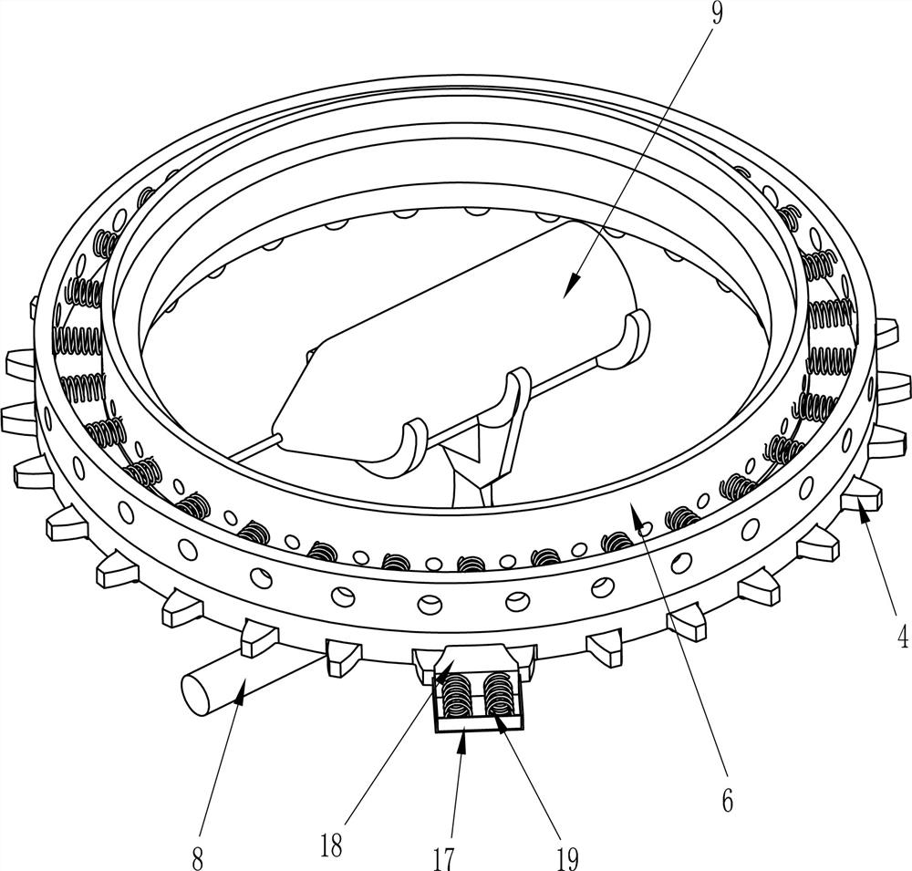
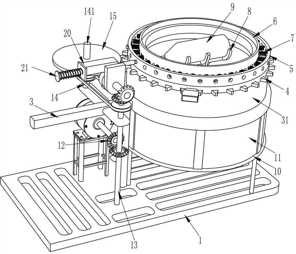
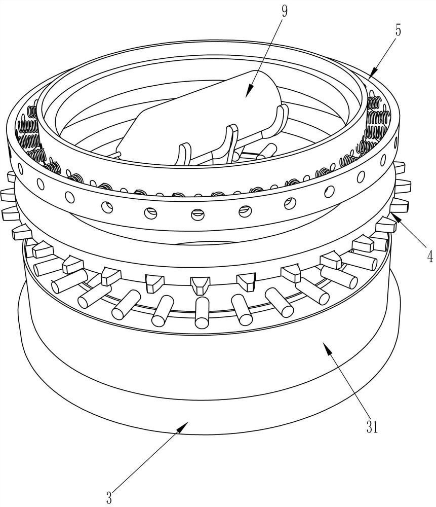
[0022] A kind of birdcage top frame automatic uniform drilling equipment, such as Figure 1-5 As shown, it includes a frame 1, a motor 2, a first support frame 3, a connecting ring 31, a ring rack 4, a second ring 6, a first ring 5, a first spring 7, a second support frame 8, Electric drill 9, third support frame 10, waste material frame 11, first straight bevel gear 12, first rotating shaft 13, transmission device 14, second rotating shaft 141, single tooth gear 15, limit rod 16, fixing mechanism and drilling Mechanism, the left side of the front part of the inner bottom wall of the frame 1 is rotationally connected with the first rotating shaft 13, and the left side of the rear part of the inner bottom wall of the frame 1 is equipped with a motor 2, and the output shaft of the motor 2 is connected with the middle part of the first rotating shaft 13 There is a first straight bevel gear 12, two first straight bevel gears 12 are meshed, a first support frame 3 is installed in t...
Embodiment 2
[0025] On the basis of Example 1, such as figure 2 , 4 with Figure 5 As shown, the fixing mechanism includes a first guide sleeve 17, a wedge block 18 and a second spring 19. The first guide sleeve 17 is connected to the lower end of the limit rod 16 on the front side, and the front and rear sides of the inner wall of the first guide sleeve 17 are connected to the second spring. Two springs 19, a wedge block 18 is connected to the rear end of the first guide sleeve 17, and the wedge block 18 is in contact with the ring rack 4.
[0026]When people drilled the top frame of the birdcage, the top frame of the birdcage was placed in the second ring 6, the motor 2 and the electric drill 9 were started, and when the single-toothed gear 15 meshed with the ring rack 4, the ring rack 4 Rotate, the tooth of ring rack 4 is positioned between the top wall and the bottom wall of wedge block 18 and contacts with it, when single-tooth gear 15 and ring rack 4 are not meshed, the top wall o...
PUM
Abstract
The invention relates to drilling device, and particularly relates to an automatic uniform drilling device for a birdcage top frame. The automatic uniform drilling device for the birdcage top frame can replace manual work and can achieve simple, convenient and rapid drilling. The automatic uniform drilling device for the birdcage top frame comprises a rack, a motor, a first supporting frame, a first rotating shaft, first right-angle bevel gears and the like, wherein the first rotating shaft is rotationally connected to the left side of the front portion of the inner bottom wall of the rack; the motor is mounted on the left side of the rear portion of the inner bottom wall of the rack; and the first right-angle bevel gears are connected to an output shaft of the motor and the middle of thefirst rotating shaft correspondingly. According to the automatic uniform drilling device for the birdcage top frame, through driving of the motor and cooperation of a single-tooth gear and an annularrack, intermittent rotation of the birdcage top frame and intermittent movement of a push rod can be achieved, the two actions are matched with each other, thus the distance between holes can be controlled, and automatic drilling is achieved.
Description
technical field [0001] The invention relates to a drilling device, in particular to an automatic uniform drilling device for a top frame of a birdcage. Background technique [0002] The current top ring of the birdcage is generally made of a mesh made of cross-connected wooden sticks, which facilitates the circulation of air in the birdcage. Holes are evenly spaced on the top to facilitate the installation of sticks, and in order to improve the convenience of stick installation, the holes on the top ring need to be evenly opened, that is to say, the distance between adjacent round holes on the top ring of the birdcage The distance is equal so that the stick can be quickly installed in the round holes on opposite sides. Now, the outer wall of the top frame of the birdcage is usually punched manually by intermittently rotating the top ring of the birdcage. The spacing between the adjacent holes is different, so it is easy to cause the line between the two opposite holes not ...
Claims
Application Information
Patent Timeline
Application Date:The date an application was filed.
Publication Date:The date a patent or application was officially published.
First Publication Date:The earliest publication date of a patent with the same application number.
Issue Date:Publication date of the patent grant document.
PCT Entry Date:The Entry date of PCT National Phase.
Estimated Expiry Date:The statutory expiry date of a patent right according to the Patent Law, and it is the longest term of protection that the patent right can achieve without the termination of the patent right due to other reasons(Term extension factor has been taken into account ).
Invalid Date:Actual expiry date is based on effective date or publication date of legal transaction data of invalid patent.

