Channel steel stacking device for constructional engineering construction

A palletizing device and construction engineering technology, which is applied in the field of channel steel palletizing devices, can solve problems such as inconvenient use, single function, and low work efficiency, and achieve the effect of ensuring work efficiency and accelerating palletizing efficiency

Inactive Publication Date: 2020-10-13
界首市天瓴建筑工程有限公司
View PDF0 Cites 1 Cited by
  • Summary
  • Abstract
  • Description
  • Claims
  • Application Information

AI Technical Summary

Problems solved by technology

[0003] The palletizer is a key equipment in the channel steel production line or channel steel processing line, and the products, specifications and production capacity of the entire production line are affected by the capacity of the palletizer. Although there are many types of steel palletizers, but Its function is often relatively simple, and a palletizer can only perform targeted palletizing of some channel steels with relatively simple specifications and structures, such as H-beams, I-beams, and channel steels.
Palletizing devices often use palletizing manipulators with electromagnets as the transport mechanism, but the existing palletizing manipulators have complex structures and are inconvenient to use, and electromagnets are used as lifting equipment for transporting section steel to demagnetize slowly, and it takes a delay to restart. Lifting, low work efficiency, delaying the normal palletizing process

Method used


Image

  • Channel steel stacking device for constructional engineering construction
  • Channel steel stacking device for constructional engineering construction
  • Channel steel stacking device for constructional engineering construction

Examples


Embodiment Construction

[0030] The following will clearly and completely describe the technical solutions in the embodiments of the present invention with reference to the accompanying drawings in the embodiments of the present invention. Obviously, the described embodiments are only some, not all, embodiments of the present invention. Based on the embodiments of the present invention, all other embodiments obtained by persons of ordinary skill in the art without creative efforts fall within the protection scope of the present invention.

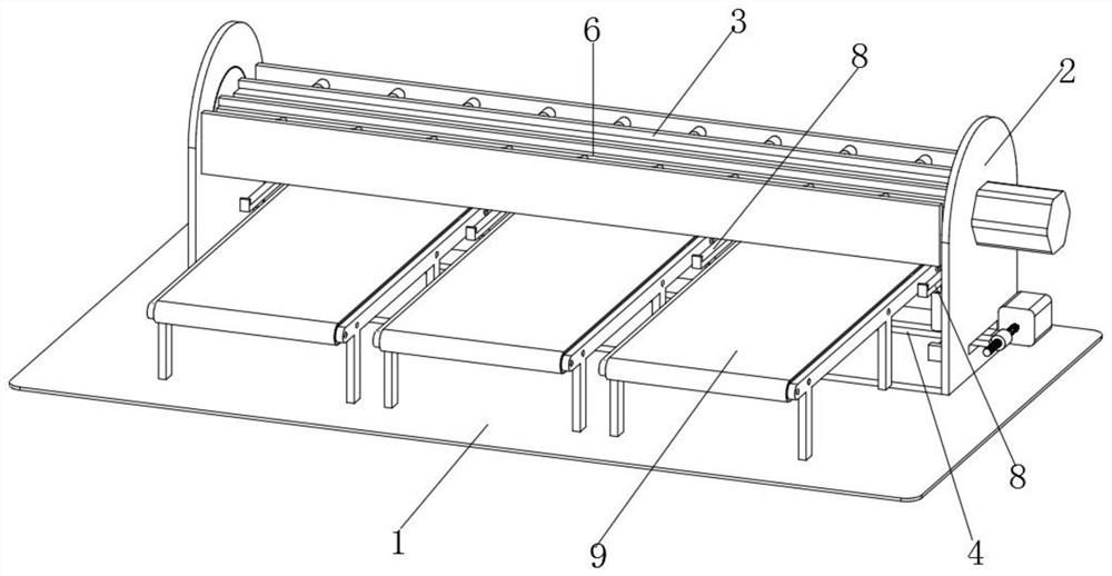
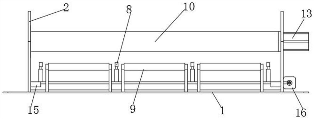
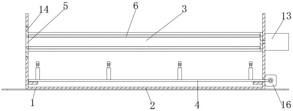
[0031] see Figure 1-8 Shown, the present invention is a kind of channel steel stacking device for building engineering construction, comprises stacking platform 1, and one side of the upper surface of stacking platform 1 is fixed with stacking rack 2, and the inner top of stacking rack 2 rotates Cooperated with a return-shaped frame 3, the inner bottom of the palletizing rack 2 is slidably fitted with a slide plate 4; one end of the return-shaped frame 3 is provid...


PUM


Abstract

The invention discloses a channel steel stacking device for constructional engineering construction, and relates to the technical field of building construction. The device comprises a stacking table,a stacking rack is fixed to one side of the upper surface of the stacking table, a concentric-square-shaped frame is rotationally matched with the inner top of the stacking rack, and a sliding plateis in sliding fit with the inner bottom of the stacking rack; a feeding port is formed in one end of the concentric-square-shaped frame, and supporting plates are arranged at the tops and the bottomsof the two opposite inner side faces of the concentric-square-shaped frame in a sliding fit mode; first extendable rods are fixed to the upper surface of the sliding plate at intervals, and a stackingframe is fixed to the top ends of the first extendable rods; and a conveying belt staggered with the stacking frame is fixed to the other side of the upper surface of the stacking table, and one endof the conveying belt extends into the stacking rack and is located below the concentric-square-shaped frame. According to the channel steel stacking device, channel steel is guided into the concentric-square-shaped frame through the feeding port, the stacking state of the channel steel is controlled through rotating the concentric-square-shaped frame, the supporting plates are pulled out outwardsto enable the channel steel to fall into the stacking frame, the channel steel stacking process is achieved, and the working efficiency of the channel steel stacking device is improved.

Description

technical field [0001] The invention belongs to the technical field of building construction, and in particular relates to a channel steel palletizing device used in building engineering construction. Background technique [0002] Building construction refers to the production activities in the implementation stage of engineering construction. It is the construction process of various buildings. It can also be said to be the process of turning various lines on the design drawings into physical objects at designated locations. It includes basic engineering construction. , main structure construction, roofing engineering construction and decoration engineering construction, etc., the construction site is called "building construction site" or "construction site", also called construction site, and the most used steel on the construction site is channel steel and pipe fittings. Channel steel is a long strip of steel with a groove-shaped cross-section. It belongs to carbon struc...

Claims


Application Information

Patent Timeline
IPC IPC(8): B65G57/06B65G57/08
CPCB65G57/06B65G57/08
Inventor 朱惜惜
Owner 界首市天瓴建筑工程有限公司
Why Eureka
Try Eureka