Steel structure cross beam splicing equipment and steel structure cross beam splicing process

A technology for steel structures and beams, which is applied to building construction, construction, and building material processing. It can solve the problems of manual calibration and alignment, labor-intensive manufacturing, and many rods and nodes, so as to improve efficiency and accuracy. The effect of sex, reducing labor intensity and simplifying the work process

Active Publication Date: 2020-10-13
冠恒建设集团有限公司
View PDF7 Cites 2 Cited by
  • Summary
  • Abstract
  • Description
  • Claims
  • Application Information

AI Technical Summary

Problems solved by technology

[0003] Since the amount of steel used in the web is less than that of the web of the solid web, the steel truss can often be made to have a larger height and thus have greater rigidity. However, the steel truss has more members and nodes, and the structure is more complicated. Manufacturing is labor-intensive, and the requirements for installation and construction equipment are relatively high. However, the following problems exist in the traditional steel structure beam assembly operation. 1. When the traditional steel structure beam assembly operation is generally performed manually The beams are placed between the steel trusses, and the relative positions of the left and right ends and the distance between the beams are manually adjusted, and fixed with clamps. Usually, the size of the steel structure trusses is long and the number of beams is large, so manual alignment is difficult
2. The traditional steel structure beam assembly equipment cannot automatically perform positioning operations during assembly, nor can it automatically place the steel structure beams to be assembled to the corresponding installation positions after positioning, and clamp and fix them, nor can it After the installation is completed, it automatically runs to the next position to be installed for continuous operation

Method used


Image

  • Steel structure cross beam splicing equipment and steel structure cross beam splicing process
  • Steel structure cross beam splicing equipment and steel structure cross beam splicing process
  • Steel structure cross beam splicing equipment and steel structure cross beam splicing process

Examples


Embodiment Construction

[0031] In order to make the technical means realized by the present invention, creative features, goals and effects easy to understand, the following combination Figure 1 to Figure 11 , to further elaborate the present invention.

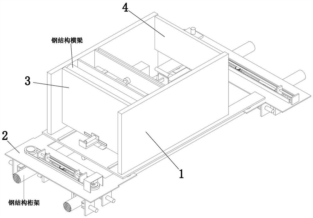
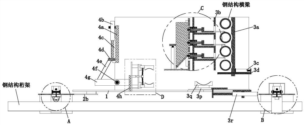
[0032] An assembly equipment for steel structure beams, comprising a mobile 匚-shaped bottom plate 1, a traveling mechanism 2, a blanking mechanism 3 and a clamping mechanism 4, the mobile 匚-shaped bottom plate 1 is placed with the opening upward, and the mobile 匚-shaped bottom plate 1 The traveling mechanism 2 is mounted on the lower side through rotation, the blanking mechanism 3 is installed between the inner walls of the two sides of the mobile bottom plate 1, and the clamping mechanism 4 is installed between the inner walls of the two sides of the mobile bottom plate 1, and the clamping mechanism 4 is located at Blanking mechanism 3 rear.

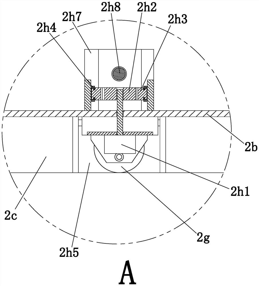
[0033] The traveling mechanism 2 includes a traveling bottom plate 2a, a traveling bottom plate 2b, a fi...


PUM


Abstract

The invention provides steel structure cross beam splicing equipment and a steel structure cross beam splicing process. The equipment comprises a moving [-shaped bottom plate, an advancing mechanism,a falling mechanism and a clamping mechanism, according to the moving [-shaped bottom plate, an opening is upwards placed, the lower portion of the moving [-shaped bottom plate is provided with the advancing mechanism in a rotation fit manner, the falling mechanism is arranged between the inner walls of the two sides of the moving [-shaped bottom plate, the clamping mechanism is arranged between the inner walls of the two sides of the moving [-shaped bottom plate, the clamping mechanism is located behind the falling mechanism, according to the steel structure cross beam splicing equipment, a design theory of an adjusting type multi-station structure is adopted for splicing a steel structure cross beam, a mechanical integrated work structure is adopted, labor intensity of a worker is reduced, the work flow is simplified, meanwhile, a drive and positioning device is mounted, and accuracy of adjusting of the cross beam placing position during steel structure cross beam splicing is improved.

Description

technical field [0001] The invention relates to the technical field of steel structure beam assembly, in particular to a steel structure beam assembly equipment and a steel structure beam assembly process. Background technique [0002] Steel truss refers to a truss made of steel. In the fields of crane beams, bridges and hydraulic gates of industrial and civil buildings, steel trusses are commonly used as the main load-bearing components. Compared with solid web beams, steel trusses use sparse web members instead of integral web plates, and the members mainly bear axial force, which can often save steel and reduce the weight of the structure. This makes steel trusses particularly suitable for structures with large spans or heights. In addition, the steel truss is also convenient to make various shapes according to different usage requirements. [0003] Since the amount of steel used in the web is less than that of the web of the solid web, the steel truss can often be made...

Claims


Application Information

Patent Timeline
Patent Type & Authority Applications(China)
IPC IPC(8): E04B1/24E04G21/16
CPCE04B1/24E04G21/16
Inventor 王兰兰鲍宪丽
Owner 冠恒建设集团有限公司
Why Eureka
Try Eureka