Supercharge Your Innovation With Domain-Expert AI Agents!

Pressure difference driven suction and discharge mechanism

A technology of differential pressure drive and drive mechanism, which is applied in machine/engine, liquid variable capacity machinery, liquid fuel engine, etc., and can solve the problems of complex pump body structure and dynamic sealing.

Active Publication Date: 2022-03-29
PENG CHENG LAB
View PDF6 Cites 0 Cited by
  • Summary
  • Abstract
  • Description
  • Claims
  • Application Information

AI Technical Summary

Problems solved by technology

[0004] The invention provides a pressure difference driven suction and discharge mechanism, which aims to solve the maintenance problems caused by the complex structure of the pump body and the dynamic seal in the prior art. for broad

Method used


Image

  • Pressure difference driven suction and discharge mechanism
  • Pressure difference driven suction and discharge mechanism
  • Pressure difference driven suction and discharge mechanism

Examples


Embodiment Construction

[0033] The following will clearly and completely describe the technical solutions in the embodiments of the present invention with reference to the accompanying drawings in the embodiments of the present invention. Obviously, the described embodiments are only part of the embodiments of the present invention, not all of them. Based on the embodiments of the present invention, all other embodiments obtained by persons of ordinary skill in the art without creative efforts fall within the protection scope of the present invention.

[0034] It should be noted that all directional indications (such as up, down, left, right, front, back...) in the embodiments of the present invention are only used to explain the relationship between the components in a certain posture (as shown in the accompanying drawings). Relative positional relationship, movement conditions, etc., if the specific posture changes, the directional indication will also change accordingly.

[0035] In addition, in t...


PUM


Abstract

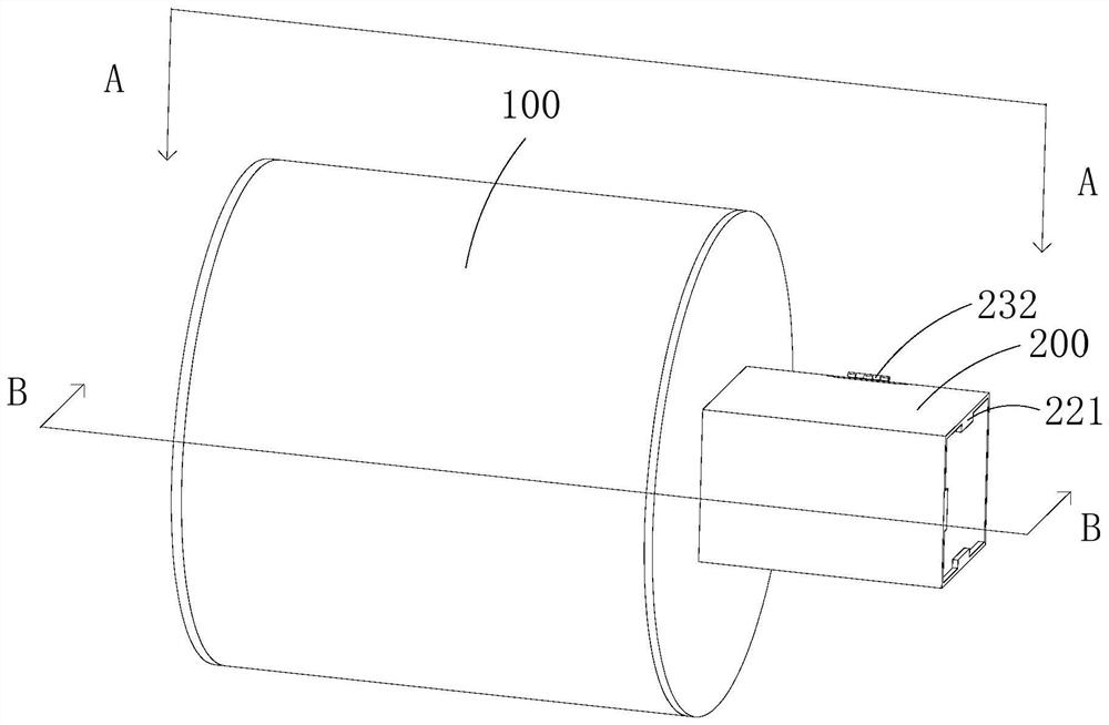
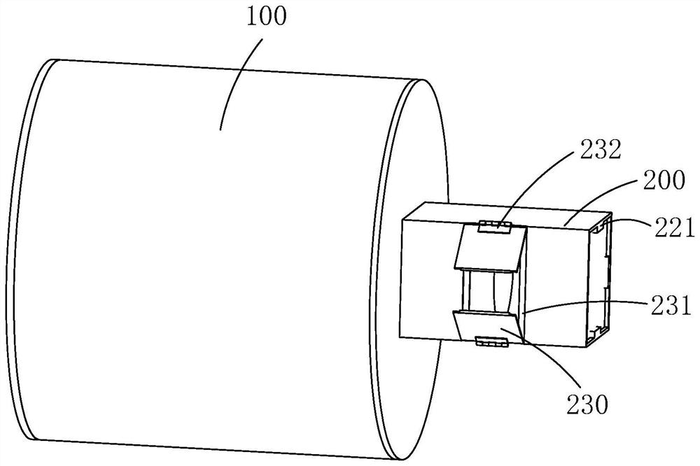
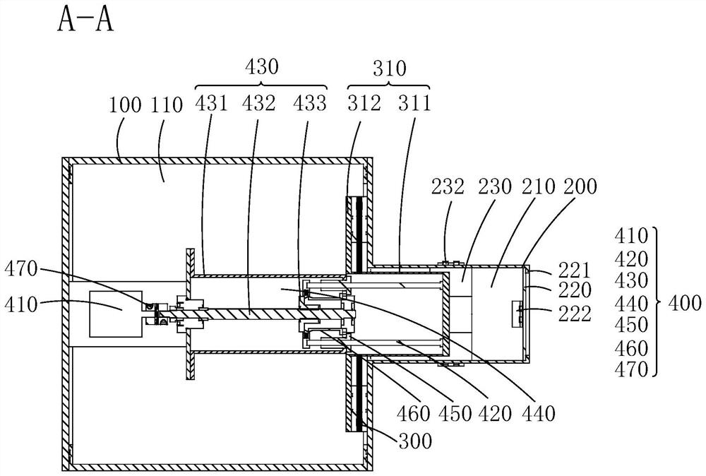
The invention discloses a differential pressure driven suction and discharge mechanism, the differential pressure driven suction and discharge mechanism includes a sealing sleeve, a suction and discharge chamber, a variable pressure cavity and a variable pressure cavity sleeve; the suction and discharge chamber and the variable pressure cavity connected; the first cavity is formed in the sealing sleeve, the variable pressure cavity is arranged in the first cavity, the variable pressure cavity is an elastic cavity, and the suction and discharge cavity formed by the suction and discharge chamber is connected with the The pressure changing cavity is connected; the suction and discharge chamber also includes an inlet baffle and an outlet baffle. The invention provides a differential pressure driven suction and discharge mechanism, which uses the difference between the pressure of the first cavity and the pressure of the variable pressure cavity as the driving force, so that the suction and discharge mechanism can adjust the working mode of the suction and discharge mechanism according to the pressure difference, so as to realize the The discharge or suction process of the above-mentioned suction and discharge mechanism. It aims to solve the complex structure of the pump body and the maintenance problems caused by the dynamic seal in the prior art. At the same time, the patent of the invention can be used as a new type of suction and discharge driver, and the application scene is wider than that of the pump.

Description

technical field [0001] The invention relates to the technical field of medium transmission, in particular to a differential pressure driven suction and discharge mechanism. Background technique [0002] A pump is a machine that conveys a medium or pressurizes a medium. It transmits the mechanical energy of the prime mover or other external energy to the medium to increase the energy of the medium. Existing pumps can be classified into positive displacement pumps, impeller pumps and jet pumps according to their working principles. [0003] When the pump body is used in the underwater environment, it is usually necessary to use the plunger pump in the positive displacement pump to realize the discharge and suction process of the medium. The volume of the working chamber changes to realize the suction and pressure of the medium. However, during the working process of the plunger pump, the plunger needs to move along the plunger rod at a certain speed. Not only the structure i...

Claims


Application Information

Patent Timeline
Patent Type & Authority Patents(China)
IPC IPC(8): F04B17/03F04B9/08F04B53/00F04B53/16
CPCF04B17/03F04B9/08F04B53/00F04B53/16
Inventor 杨仁友林静张爱东侯西龙王超张荣誉
Owner PENG CHENG LAB
Features
  • R&D
  • Intellectual Property
  • Life Sciences
  • Materials
  • Tech Scout
  • Unparalleled Data Quality
  • Higher Quality Content
  • 60% Fewer Hallucinations
Learn More