Automatic measuring system for grating diffraction angle spectrum

A grating diffraction and automatic measurement technology, which is applied in the field of optical measurement, can solve the problems that cannot meet the requirements of diffraction angle spectrum measurement, can not measure diffraction angle, and diffraction efficiency accurately, and achieve the effect of high signal-to-noise ratio and high dynamic range

Active Publication Date: 2020-10-13
SHENZHEN INST OF ADVANCED TECH
View PDF9 Cites 1 Cited by
  • Summary
  • Abstract
  • Description
  • Claims
  • Application Information

AI Technical Summary

Problems solved by technology

[0003] In the prior art, measuring the diffraction efficiency of the working order of the grating cannot meet the requirements of the diffraction angle spectrum measurement, such as patent application CN201711430637 (a grating diffraction efficiency test system and method) and patent application CN201611039171 (grating diffraction efficiency spectral measurement device and measurement method)
Since the grating is used for dispersion, only a specific diffraction order (that is, the working order, generally +1 order or -1 order) is often used, and the prior art is all about measuring the relationship between the diffraction efficiency of the grating working order and the wavelength. , to evaluate the effective wavelength range of the grating, but it is not possible to accurately measure the diffraction angle and diffraction efficiency of each order

Method used


Image

  • Automatic measuring system for grating diffraction angle spectrum
  • Automatic measuring system for grating diffraction angle spectrum
  • Automatic measuring system for grating diffraction angle spectrum

Examples


Embodiment Construction

[0023] Various exemplary embodiments of the present invention will now be described in detail with reference to the accompanying drawings. It should be noted that the relative arrangements of components and steps, numerical expressions and numerical values ​​set forth in these embodiments do not limit the scope of the present invention unless specifically stated otherwise.

[0024] The following description of at least one exemplary embodiment is merely illustrative in nature and in no way taken as limiting the invention, its application or uses.

[0025] Techniques, methods and devices known to those of ordinary skill in the relevant art may not be discussed in detail, but where appropriate, such techniques, methods and devices should be considered part of the description.

[0026] In all examples shown and discussed herein, any specific values ​​should be construed as illustrative only, and not as limiting. Therefore, other instances of the exemplary embodiment may have dif...


PUM

PropertyMeasurementUnit
grating periodaaaaaaaaaa

Abstract

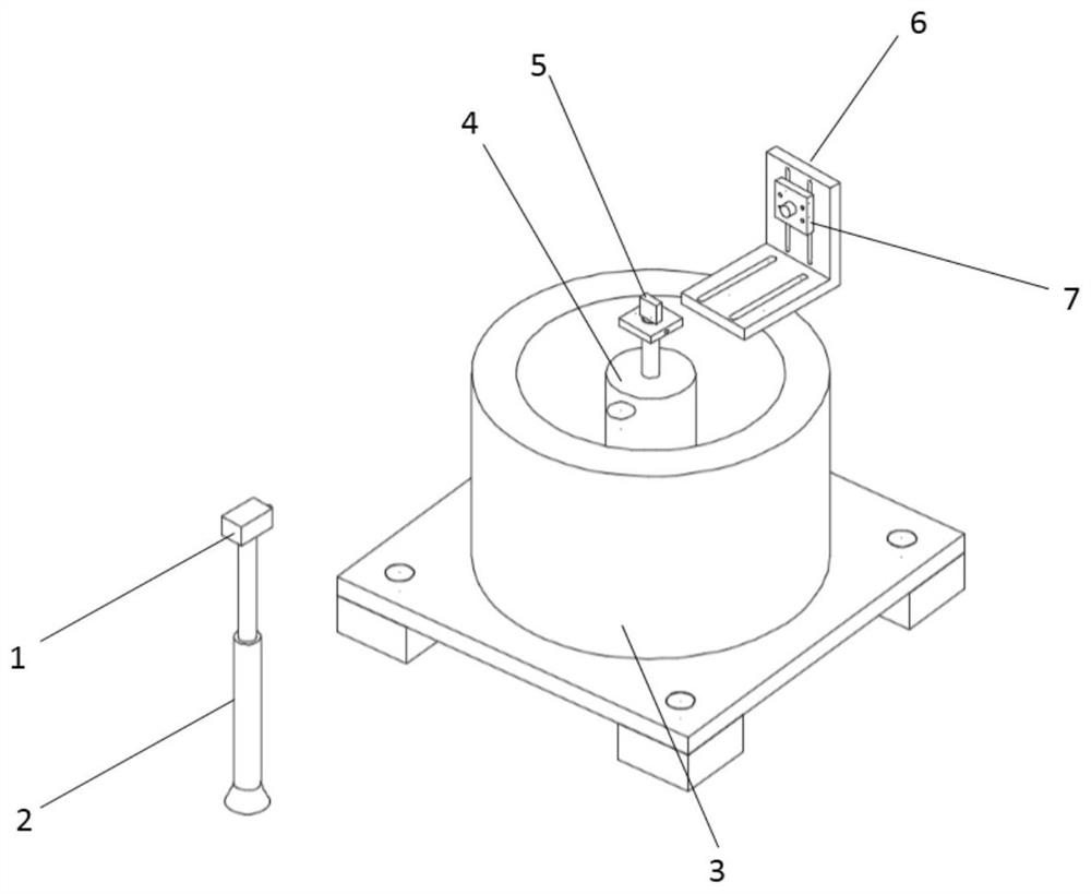
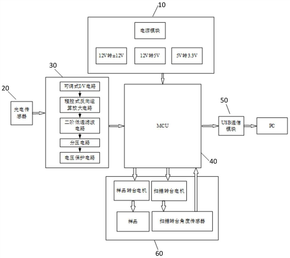
The invention discloses an automatic measuring system for a grating diffraction angle spectrum. The system comprises a laser source, a scanning turntable, a sample turntable, a photoelectric sensor, asensor bracket and a photoelectric signal detection device, wherein the laser source is placed on a bracket with adjustable height, the sensor bracket is used for bearing the photoelectric sensor, the sample turntable is used for bearing a grating to be detected, and the photoelectric signal detection device is configured to control the scanning turntable and the sample turntable to rotate at a preset rotation angle so as to adjust the incident angle of the grating to be detected and carry out grating diffraction angle spectrum scanning to obtain a grating diffraction angle spectrum measurement result. Diffraction angle spectrum measurement under different incident angles can be carried out, the diffraction efficiency of each level of the grating and the stray light condition between diffraction levels can be accurately measured, and the magnitude difference of diffraction light and stray light can be accurately reflected.

Description

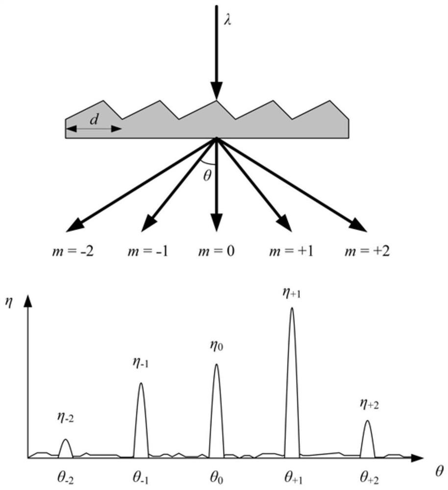
technical field [0001] The invention relates to the technical field of optical measurement, and more specifically, to an automatic measurement system for grating diffraction angle spectrum. Background technique [0002] Diffraction grating is an important optical device that diffracts incident light into multiple orders through periodic grid lines. like figure 1 As shown, the collimated light beam with a wavelength of λ is diffracted after entering the grating at a certain angle, and the diffracted light of different orders has different diffraction angles θ in space m and different diffraction efficiencies η m (diffracted light intensity divided by incident light intensity). Diffraction angle spectrum refers to the distribution of light diffracted by the grating with the angle, which is closely related to the microscopic information of the grating. First, the grating period d can be calculated by substituting the measured diffraction angle into the grating equation; sec...

Claims


Application Information

Patent Timeline
Patent Type & Authority Applications(China)
IPC IPC(8): G01M11/02
CPCG01M11/02G01M11/0214
Inventor 余明林慧马翠赖厚湖
Owner SHENZHEN INST OF ADVANCED TECH
Why Eureka
Try Eureka