Display device and electronic equipment

A technology for display devices and fixed casings, applied in identification devices, mechanical equipment, transmission devices, etc., can solve problems such as inability to fit flexible screens, affect screen flatness, and slippage between flexible screens and shaft surfaces

Pending Publication Date: 2020-10-13
BOE TECH GRP CO LTD
View PDF9 Cites 10 Cited by
  • Summary
  • Abstract
  • Description
  • Claims
  • Application Information

AI Technical Summary

Problems solved by technology

[0004] However, in the process of implementing the present application, the inventors found that there are at least the following problems in the prior art: on the one hand, the flexible screen cannot be in contact with the outer surface of the rotating shaft because of the deformation resistance generated by the internal stress during the rotation of the flexible screen around the rotating shaft. The surface fit

Method used


Image

  • Display device and electronic equipment
  • Display device and electronic equipment
  • Display device and electronic equipment

Examples


Embodiment 1

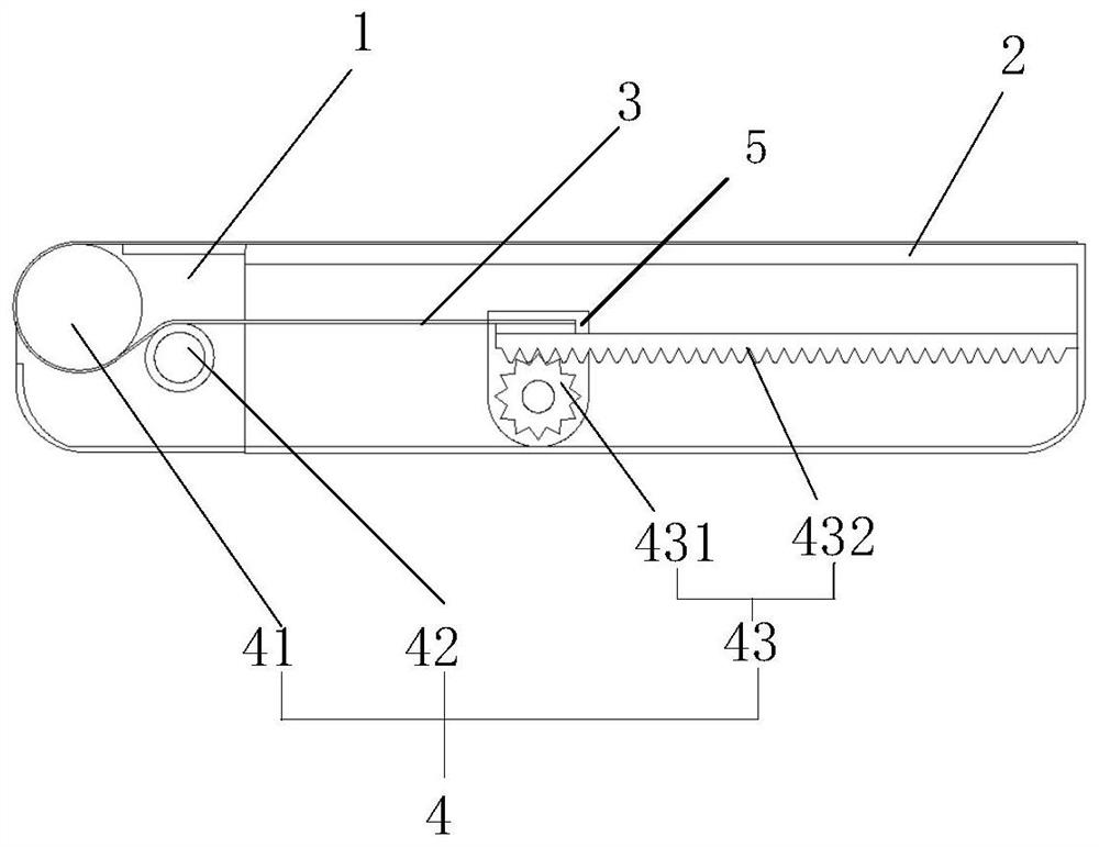
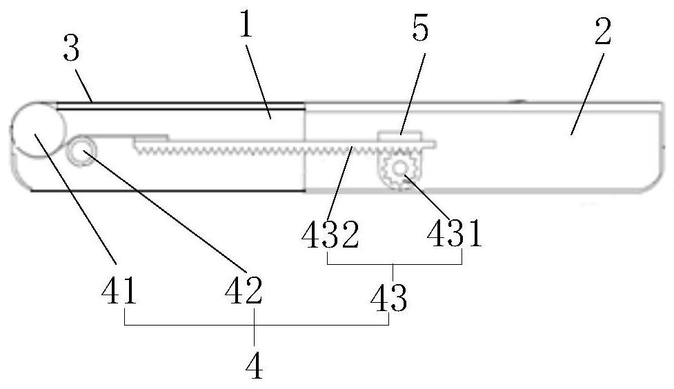
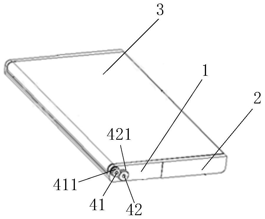
[0041] Embodiment 1 of the present invention provides a display device, referring to Figure 1 ~ Figure 2 , showing a schematic structural view of a display device of the present invention, such as Figure 1 ~ Figure 2 As shown, the display device includes a sliding casing 1, a fixed casing 2, a flexible screen 3 and a transmission assembly 4; the sliding casing 1 and the fixed casing 2 are slidably connected; the transmission assembly 4 includes a roller 41, a pretension shaft 42, The transmission part 43; the transmission part 43 is fixed inside the fixed casing 2, the first end of the flexible screen 3 is fixed on the fixed casing 2, the flexible screen 3 covers the top outer surface of the fixed casing 2, and the second end of the flexible screen 3 The end is wound around the roller 41 and fixed on the transmission member 43 , the pretension shaft 42 is located between the roller 41 and the transmission member 43 , and the top outer surface of the pretension shaft 42 press...

Embodiment 2

[0071] Embodiment 2 of the present invention also provides an electronic device, the electronic device includes the display device described in any one of the above implementations, the beneficial effect of the electronic device is consistent with the beneficial effect of the above display device, and the embodiment of the present invention is This will not be repeated here.

[0072] It should be noted that the electronic device may be: a mobile phone, a tablet computer, an e-book reader, an MP3 player, an MP4 player, a laptop computer, a vehicle computer, a desktop computer, a set-top box, a smart TV or a wearable device , which is not limited in this embodiment of the present invention.


PUM


Abstract

The embodiment of the invention provides a display device and electronic equipment, and belongs to the technical field of display. The display device comprises a sliding machine shell, a fixed machineshell, a flexible screen and a conveying assembly. The sliding machine shell is in sliding connection with the fixed machine shell. The conveying assembly comprises a rolling shaft, a pre-tighteningshaft and a transmission part. The rolling shaft and the pre-tightening shaft are both hinged to the sliding machine shell. The transmission part is fixed in the fixed machine shell. A first end of the flexible screen is fixed to the fixed machine shell, the flexible screen covers the outer surface of the top of the fixed machine shell, and a second end of the flexible screen winds the rolling shaft and is fixed to the transmission part. The pre-tightening shaft is located between the rolling shaft and the transmission part, and the outer surface of the top of the pre-tightening shaft abuts against the flexible screen. Thus, the outer surface of the pre-tightening shaft abuts against the flexible screen all the time, the contact area between the flexible screen and the rolling shaft is increased, meanwhile, the flexible screen is always subjected to supporting force of the pre-tightening shaft, and the flexible screen can be always matched with the outer surface of the rolling shaft under the effect of the supporting force of the pre-tightening shaft.

Description

technical field [0001] The present invention relates to the field of display technology, in particular to a display device and electronic equipment. Background technique [0002] With the continuous development of display technologies, users have increasingly diverse demands on display effects of display devices. With the application of flexible display screens, display devices are increasingly pursuing practicability and personalization, such as changing the display ratio of the display device to realize switching between different functional modes of the display device. [0003] At present, the display device includes a flexible screen and a device casing, and a rotating shaft is arranged in the device casing, the first end of the flexible screen is fixed on the device casing, and the second end of the flexible screen is wound around the rotating shaft, and rotates through the rotating shaft , the area covered by the flexible screen on the device casing can be changed to ...

Claims


Application Information

Patent Timeline
IPC IPC(8): G09F9/30F16H19/04
CPCG09F9/301F16H19/04Y02D10/00
Inventor 王宗元刘小林刘君欢祝尚杰
Owner BOE TECH GRP CO LTD
Why Eureka
Try Eureka