
Positioning machine capable of automatically finding power installation point for electric power engineering positioning

A technology of power engineering and installation points, which is applied in the direction of manufacturing tools, workpiece clamping devices, electromagnetic wave reradiation, etc., can solve problems such as complex terrain, unfavorable work efficiency, inaccurate measurement data of leather tape, etc., to achieve accurate data and improve Effect of Spacing Dimensions

Active Publication Date: 2020-10-16
山东广瑞电力科技有限公司
View PDF10 Cites 1 Cited by
  • Summary
  • Abstract
  • Description
  • Claims
  • Application Information

AI Technical Summary

Problems solved by technology

[0004] Aiming at the deficiencies of the prior art, the present invention provides a positioning machine for electric power engineering positioning that can automatically find the power installation point, which solves the problem that the distance positioning between the power pipes and racks proposed in the above background technology is usually measured by a leather tape measure However, the leather tape measure needs to be retracted and retracted continuously during use, which is not conducive to improving work efficiency, and because the land is completely opened, there will be water in the trench that is easy to infiltrate and dirty the leather tape measure, and the terrain inside the trench is complex and easy to cause The problem of inaccurate measurement data of the leather tape measure

Method used


Image

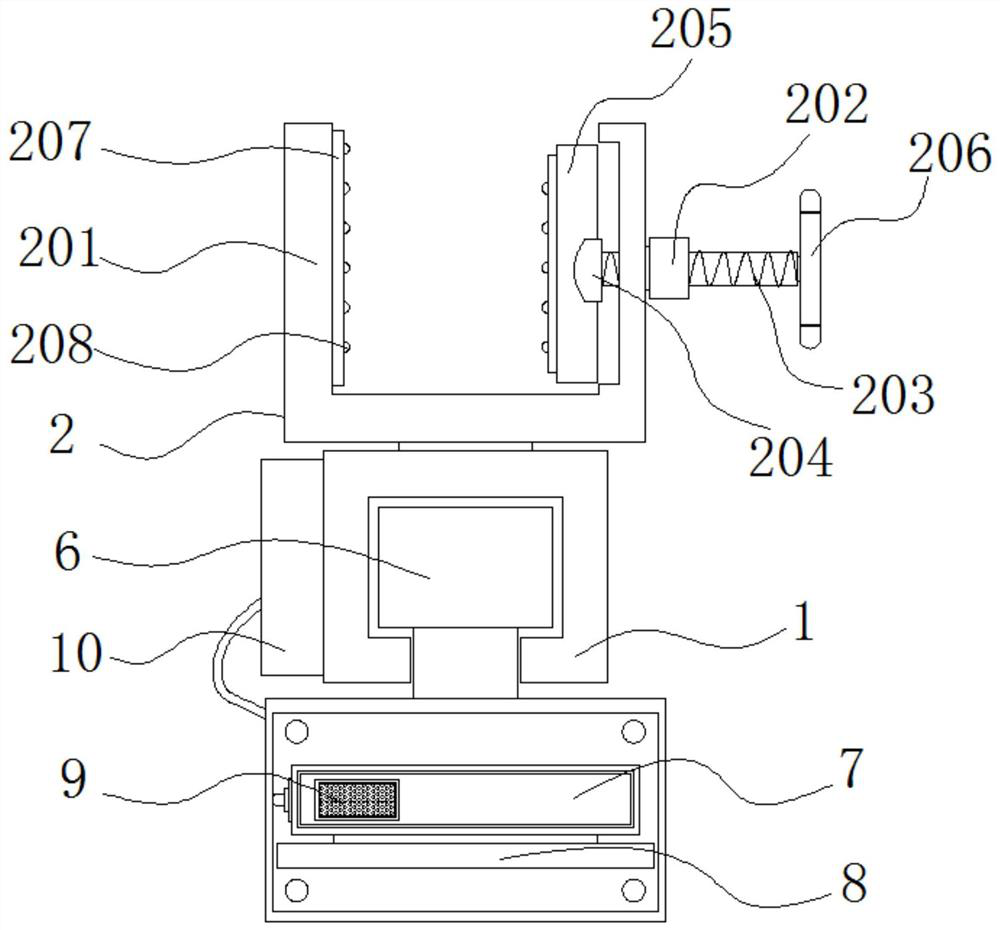
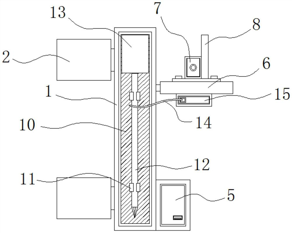
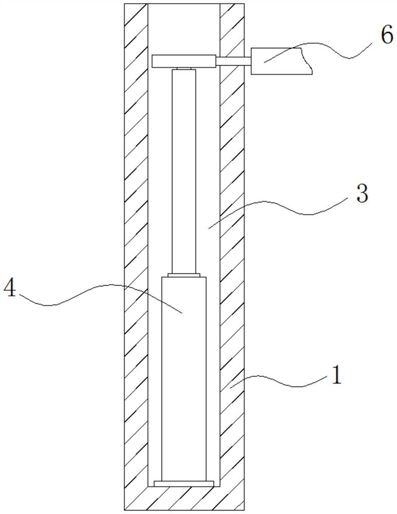
  • Positioning machine capable of automatically finding power installation point for electric power engineering positioning
  • Positioning machine capable of automatically finding power installation point for electric power engineering positioning
  • Positioning machine capable of automatically finding power installation point for electric power engineering positioning

Examples


Embodiment Construction

[0027] The following will clearly and completely describe the technical solutions in the embodiments of the present invention with reference to the accompanying drawings in the embodiments of the present invention. Obviously, the described embodiments are only some, not all, embodiments of the present invention.

[0028] In the description of the present invention, unless otherwise stated, the meaning of "plurality" is two or more; the terms "upper", "lower", "left", "right", "inner", "outer" , "front end", "rear end", "head", "tail", etc. indicate the orientation or positional relationship based on the orientation or positional relationship shown in the drawings, and are only for the convenience of describing the present invention and simplifying the description, rather than Nothing indicating or implying that a referenced device or element must have a particular orientation, be constructed, and operate in a particular orientation should therefore not be construed as limiting ...


PUM


Abstract

The invention discloses a positioning machine capable of automatically finding a power installation point for electric power engineering positioning, and relates to the technical field of power pipe rack installation and positioning. The positioning machine particularly includes a vertical column, soil inserting rods, and a winding box. The interior of the vertical column is fixed with a clampingmechanism. The bottom of the outer side of the vertical column is provided with a battery box. The front of a laser range finder is connected with a control panel. The soil inserting rods are mountedinside clamping parts. The surfaces of the soil inserting rods are bound with detection lines. The winding box is mounted on one end of the detection lines. The positioning machine is capable of automatically finding a power installation point. When data obtained by the laser range finder is identical to a default value of a light barrier, and a horn stand bone beeps, the soil inserting rods are inserted into soil. The positions of the soil inserting rods are positions for installing a power pipe rack. The positioning machine capable of automatically finding the power installation point for electric power engineering positioning is conducive to the automatic and accurate positioning of the distance between power pipe racks and prevents power pipes from falling down after the power pipes are mounted on the power pipe racks.

Description

technical field [0001] The invention relates to the technical field of installation and positioning of power pipe racks, in particular to a positioning machine for electric power engineering positioning that can automatically find power installation points. Background technique [0002] Electric power engineering refers to projects related to the production, transmission and distribution of electric energy, which naturally includes the laying of underground cables. At present, the main process of laying underground cables is, Backfilling, the distance between the power pipe racks is often closely related to the length of the power pipes. If the distance between the power pipe racks is too large, the middle of the power pipe will sag, and if the distance between the power pipe racks is too short, it will cause the power pipes to sag. The two ends are drooping, so the distance between the power pipe racks needs to be positioned when the power pipe racks are laid. [0003] At ...

Claims


Application Information

Patent Timeline
Patent Type & Authority Applications(China)
IPC IPC(8): B25B11/00H02G1/08G01S17/08
CPCB25B11/00G01S17/08H02G1/08
Inventor 兰新伟
Owner 山东广瑞电力科技有限公司
Learn More